The template kinematics can be created for a specific category of machine (e.g., 3-Axis), which can then be used to build quickly any number of machines belonging to a similar category. It thus parameterizes the creation of machine models, without duplicating the effort.
Additionally this method provides a way of creating V5 machine models using machine geometry from an external CAD system.
This procedure has the following parts:
Defining the Template
-
Click New Machine
 .
. -
Click Fixed Part
 .
.The New Fixed Part dialog box is displayed. 
-
Select the FixedPart_DU product from the specification tree or from the geometry area.
The FixedPart_DU leaf appears in the specification tree under the Mechanisms node. -
Click Prismatic Joint
 .
.The Joint Creation Prismatic dialog box appears (the image below shows the dialog box once it contains the correct information). 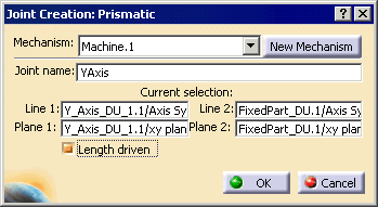
-
Enter YAxis in the Joint name field.
-
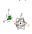
Select the Y axis of YAxis_DU_1 for Line1, and select Y axis of FixedPart_DU (AxisSystem.1) for Line2.
-
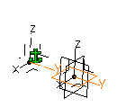
Select the XY plane of YAxis_DU_1 for Plane1, and select XY plane of FixedPart_DU (AxisSystem.1) for Plane2.
-
Select the Length driven checkbox, and click OK.
An Information message appears. 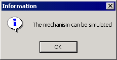
-
Click OK.
-
Use the table below for information on creating two other prismatic joints or revolute joint. In all cases, select the Length driven checkbox or Angle driven checkbox.
Joint Name Joint Type Line1 Line2 Plane1 Plane2 Part 1 Part 2 ZAxis  Prismatic
Z axis Z axis ZX Plane ZX Plane ZAxis_DU_1 YAxis_DU_1 XAxis  Prismatic
X axis X axis XY Plane XY Plane XAxis_DU_1 FixedPart_DU (AxisSystem 2) CAxis  Revolute
Z axis Z axis XY Plane XY Plane CAxis_DU_1 XAxis_DU_1 -
Define the tool mount part and point as the ZAxis_DU_1.
-
Double-click on the Tool Mount Point leaf on the specification tree.
-
Select the compass by the red square and move it to the ZAxis_DU_1 part; position it as shown.
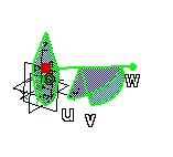
-
On the specification tree, click on the ZAxis_DU_1 part node.
The Set Location dialog box appears. -
Click OK.
-
-
Define the workpiece mount part and point as the CAxis_DU_1 part.
-
Double-click on the Workpiece Mount Point leaf on the specification tree.
-
Select the compass by the red square and move it to the CAxis_DU_1 part; position it as shown.

-
On the specification tree, click on the CAxis_DU_1 part node.
The Set Location dialog box appears. -
Click OK.
-
-
Save the .CATProduct file for later use as a template.
Adding the Parts for Dressup
-
Right-click on the DressupMachine node at the top of the specification tree, and select Components > Existing Components.
-
Navigate to the online/mtbug_C2/samples/V5/Mechanism_Dressup directory.
-
Select the following parts:
- ZAxis.CATPart
- CTable.CATPart
- XAxis.CATPart
- YAxis.CATPart
- Base.CATPart
-
Select all of the _DU components and click Hide/Show
 .
. -
Position the parts per the template parts.
-
Right-click on the compass, and select Snap Automatically to Selected Object.
-
Select the Base part.
The compass snaps to the part when it is selected. -
Right-click on the compass, and select Edit.
The Parameters for Compass Manipulation dialog box appears. -
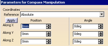
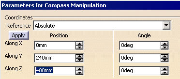
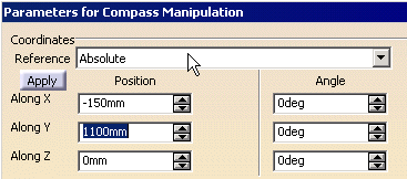
Position and orient the parts so that the options in the dialog box are those as shown below.

-
Select each of the other parts and position according to the dialog boxes shown below.
YAxis part
ZAxis part
XAxis part
Ctable part
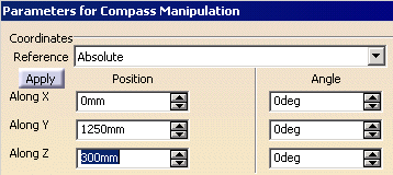
-
-
The Mechanism Dressup dialog box appears. 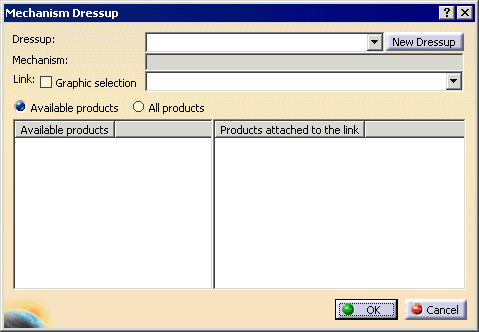
-
Click the New Dressup button.


This step indicates the mechanism on which the dressup is to be defined. -
Click OK.
The Mechanism Dressup dialog box refreshes so that the Available products list contains the products defined above. The products need to be linked with the already defined mechanism. 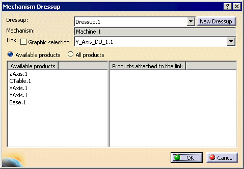
-
In the Link list, select FixedPart_DU.1, and from Available products, select Base.1.
-
Repeat for the remaining products using the table below.
Link Available product Z_Axis_DU_1.1 ZAxis.1 Y_Axis_DU_1.1 YAxis.1 X_Axis_DU_1.1 XAxis.1 C_Axis_DU_1.1 CTable.1 FixedPart_DU.1 Base.1 -
Click OK.