Multi-Slide Lathe Machine
This section deals with the multi-slide lathe machine that is available when
the Multi-Slide Lathe Machining add-on product is installed in the Lathe
Machining workbench. It describes:
Machine Capabilities for the Multi-Slide
Lathe Machine
Multi-slide lathe machine comprises a number of spindles and turrets, which
you specify in the Machine editor dialog box.
In the Turret and Spindle tabs of this dialog box, the presentation is
similar:
- On the left, the list of turrets and spindles with command buttons to add
or remove these entities.
There must always be a minimum of one turret and one spindle.
- On the right, properties of the selected element are displayed.
Note that addition of turrets and spindles is only possible when Multi-Slide
Lathe Machining is installed.
Turret Definition
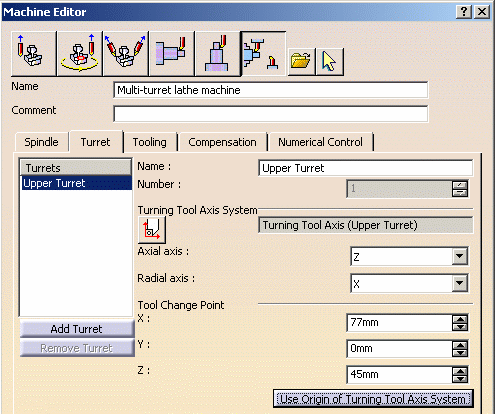
Here is an example of the Turret tab:

Each turret has a name, which will be displayed in the PPR tree next to the
program with which it is associated.
Each turret has a number, which is output in APT output in place of
MFG_CHANNEL_NUMBER in the program header or synchronization syntax.
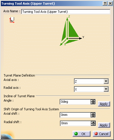
You can specify the Turning Tool Axis System by clicking
 in the dialog box.

The Axial and Radial axes of this axis system define the working plane of
the turret for turning operations: tool path, replay, and time based replay are
represented in this plane.
This axis system can be any axis system. However, the working plane must
contain the spindle axis that the turret works on.
At the bottom of the Turning Tool Axis System dialog box:
- The angle defines the incline of the Turret Plane with respect to the ZX
plane of the first spindle (that is, the Setup axis system).
- Radial and axial shift give the position of the origin of the axis system
relative to the origin of the first spindle (that is, the origin of the Setup
axis system).
For more information, see Axis Systems for Part
and Turning Tool.
Tool Change point can be defined manually through its absolute coordinates
(X,Y,Z). Since this point might be considered as the origin of the Turning Tool
Axis System, you can use the button at the bottom of the Machine Editor to
automatically set it.
Spindle Definition
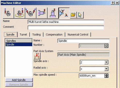
Here is an example of the Spindle tab:

Each spindle has a name, which will be displayed at the bottom of operation
editor. Note that this is the case when there is more than one spindle on the
machine. Otherwise the single spindle is used by default. It is output in APT
in place of MFG_SPINDLE_NAME.
Each spindle has a number, which is written in valuated in APT in place of
MFG_SPINDLE_NUMBER.
Spindle name and number can be valuated in NC_MACHINING_AXIS and
NC_ACTIVITY_HEADER syntaxes .
Part Axis System defines the plane where tool path, replay, and time based
replay are represented.
For more information, see Axis Systems for Part and
Turning Tool.
Maximum Spindle Speed is taken into account for time computation in
Machining Gantt Chart.
Resource Attributes for the Multi-Slide Lathe
Machine
The Multi-Slide Lathe Machine (CATEMfgMultiTurretLatheMachine) resource
attributes are described below.
Base Attributes
These attributes provide general information.
MFG_NAME (Name)
Type:
String
Specifies the name of the resource. |
MFG_COMMENT
       (Comment)
Type: String
Associates a comment to the resource. |
Numerical Control Attributes
These attributes characterize the machine controller and have an impact on
the output format.
MFG_PP_WORD_TBL
       (Post Processor words table)
Type: String
Specifies the name of the PP words table which is used for creating Post
Processor word syntaxes. |
MFG_OUTPUT_TYPE (NC
       data type)
Type: String
Possible values:
APT
CLF-3000
CLF-15000
ISO
Specifies the type of NC data output by the application. It can take the
following values: APT (APT source, this is the default), CLF-3000 (clfile
record types 3000 and 5000 are output), CLF-15000 (clfile record type
15000 is output), ISO. |
MFG_OUTPUT_FRMT (NC
       data format)
Type: String
Possible values:
POINT (Point (X,Y,Z))
AXIS (Axis (X,Y,Z,I,J,K))
Specifies the format of the NC data output. It can take the following
values: POINT (X,Y,Z point coordinates, by default), AXIS (X,Y,Z,I,J,K
point coordinates and tool axis components). |
MFG_STRT_PT_SYNT
       (Home point strategy)
Type: String
Possible values:
FROM (FROM)
GOTO (GOTO)
Specifies the type of trajectory on the start point: GOTO or FROM |
MFG_MAX_FEEDRATE
       (Max machining feedrate)
Type: Real
Specifies the maximum machining feedrate. This is used in NC
Manufacturing Verification Product Errors (tool collision with the stock)
will be reported if the feedrate exceeds this value |
MFG_RAPID_FEED
       (Rapid feedrate)
Type: Real
Specifies the rapid feedrate. This is used to compute the total machining
time and may replace the RAPID instruction in output APT files. |
MFG_AXIAL_RADIAL_MOVE (Axial/Radial movement)
Type: Boolean (Yes/No)
Specifies the ability to generate automatically axial and radial
movements to avoid collisions in axial operations |
MFG_INT_LIN_3D (3D
       linear interpol.)
Type: Boolean (Yes/No)
Specifies if the machine is able to make a 3D linear interpolation
between 2 points. |
MFG_INT_CIRC_2D (2D
       circular interpol.)
Type: Boolean (Yes/No)
Specifies if the machine is able to make a 2D circular interpolation
between 2 points. |
MFG_INT_CIRC_3D (3D
       circular interpol.)
Type: Boolean (Yes/No)
Specifies if the machine is able to make a 3D circular interpolation
between 2 points. |
MFG_R_MIN_CIRC (Min
       interpol. radius)
Type: Real
Specifies the minimum radius of circular interpolation that the machine
is able to achieve. |
MFG_R_MAX_CIRC (Max
       interpol. radius)
Type: Real
Specifies the maximum radius of circular interpolation that the machine
is able to achieve. |
MFG_MIN_DISC (Min
       discretization step)
Type: Real
Specifies the minimum distance between two consecutive points that the
machine is able to achieve.Note:
The application compares the minimum discretization step and the
machining tolerance. The larger of the two values is taken to be the
minimum distance between two points.
When you generate NC data, any points that are spaced at a distance
less than this value are eliminated from the output file. |
MFG_MIN_ANGLE (Min
       discretization angle)
Type: Real
Specifies minimum angle between tool axis at two consecutive points that
the machine is able to achieve. The application eliminates points whose
tool axis orientation does not meet this criteria. |
Spindle Attributes
These attributes provide information on the spindle and have an impact on
spindle capabilities.
| MfgLmtSpindleName
(Spindle name)
Defines the name of the spindle, output in NC code. |
| MfgLmtSpindleNumber
(Spindle number)
Defines the number of the spindle, output in NC code. |
| PAS (Part axis system)
Defines the Part axis system on a spindle. |
MFG_LATHE_RAD_AX
       (Radial axis)
Type: String
Possible values:
X
Y
Z
Defines the radial axis, which is generally the X axis.
Combined with the spindle axis, it defines the programming working plane,
where the selected geometry is projected. |
MFG_LATHE_SPN_AX
       (Spindle axis)
Type: String
Possible values:
X
Y
Z
Defines the spindle and C axes, which is generally the Z axis.
Combined with the radial axis, it defines the programming working plane
where the selected geometry is projected. |
MFG_LATHE_MAX_SPNDL_SPEED
(Max spindle speed)
Type: Real
Defines the maximum speed of the spindle. It is used in time
computations when machining at constant cutting speed. |
Turret Attributes
These attributes provide information on the turret definition and have an
impact on turret capabilities.
| MfgLmtTurretName (Turret
name)
Defines the name of the turret, output in NC code. |
| MfgLmtTurretNumber
(Turret number)
Defines the number of the turret, output in NC code. |
| TAS (Turning Tool axis
system)
Defines the Turning Tool axis system on a turret. |
MFG_LATHE_RAD_AX
       (Radial axis)
Type: String
Possible values:
X
Y
Z
For a given turret, it defines the radial axis of the Turning Tool axis
system, which is generally the X axis.
Combined with the axial axis, it defines the plane where Turning tooling
is represented. |
MFG_LATHE_AX_AX
       (Axial axis)
Type: String
Possible values:
X
Y
Z
Defines the axial axis of the Turning Tool axis system, which is
generally the Z axis.
Combined with the radial axis, it defines the plane where Turning tooling
is represented. |
MFG_X_TOOL_POS (Tool
change point X)
Defines the X coordinate of the tool change point with respect to the
reference machining axis system. |
MFG_Y_TOOL_POS (Tool
change point Y)
Defines the Y coordinate of the tool change point with respect to the
reference machining axis system. |
MFG_Z_TOOL_POS (Tool
change point Z)
Defines the Z coordinate of the tool change point with respect to the
reference machining axis system. |


![]() in the dialog box.
in the dialog box.
