 |
This task shows how to review the machining
process using a Machining Gantt chart. This chart provides an overview of
all programs to optimize programming times and an easy way to manage
synchronizations between programs. |
 |
When you invoke the Machining Gantt Chart
command, start times and durations of machining activities are computed.
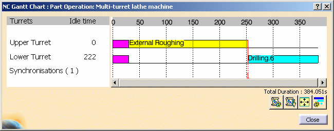
The displayed chart gives information for each turret.
- Activities of each program are displayed by means of a colored bar
as a function of time
- Synchronizations are numbered and are represented by a red vertical
line
- Operations can be accessed for edition, replay, and so on
- Idle time is given for each program.
Diagnostics are displayed in case of incompatible conditions. |
 |
1. |
Click Machining Gantt Chart
 .
The following synchronized Gantt chart appears. .
The following synchronized Gantt chart appears.

|
|
2. |
You can right click the red synchronization line in the chart to
access contextual commands: Definition: gives access to the
Synchronization dialog box.
Delete: removes the synchronization between the two
operations.
Note that dynamic short help information is given for each activity
when you pass the cursor over the graphic representation.
The time units can be customized under Tools > Options > Parameters
and Measures. |
|
3. |
The commands in the dialog box are as follows:
 Update Times: updates times (after a modification, for
example)
 Reframe Gantt Chart: reframes the Gantt chart in the viewer
 Hide or Show Diagnostics
 Update Diagnostics.
 |
 |
|
Please note the following points:
- When a synchronized machining operation is cut or copied then
pasted, the pasted operation is not synchronized.
- During a time based replay, a vertical blue line is displayed in
the Gantt chart, which allows you to follow the progress of the
machining. However, when a zoom is applied in the Gantt chart, the blue
vertical line does not take into account the zoom scale and so may not
give expected behavior.
- If the referenced machine has more than one spindle, a checkbox
entitled Color by spindle is available in the Gantt Chart
dialog box. If colors have been assigned to the machining activities
and the spindles:
- when the checkbox is not selected, the displayed bars are colored
according to the activity color.
A machining activity can be assigned a color as described in
How to Use Properties of a Machining Operation.
- when the checkbox is selected, the displayed bars are colored
according to the spindle color.
A spindle can assigned a color by right clicking the spindle resource
in the Resource List, selecting Properties, then defining
the desired color in the Graphic tab of the Properties dialog box.
- In some turning operations, linking macros are interruptible.
If such an operation is interrupted, this is not represented or taken
into account in the Machining Gantt Chart.
- Support of Master/Slave definition for time computations
with respect to instantaneous spindle speed.
When 2 turning
activities assigned on 2 different turrets work on the same spindle,
the spindle has only one speed at a given time. There is always a
master and one or more slaves. The duration of slave elements tool
paths (motions, delays, and so on) must be calculated according to the
instantaneous spindle speed.
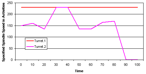
As shown in the example below, the spindle speed specified on the 2
activities is seldom the same.

When an element of tool path is Master, it uses the spindle
speed defined on the operation.
When an element of tool path is Slave, it uses the instantaneous
speed of the spindle. It only applies to Turning operations and
Drilling operations along the spindle axis.
For each spindle, this capability:
- detects slave and master elements of tool path and calculates
their duration in context
- detects possible incompatibilities (no master or several masters
defined at the same time).
|
|
 |

