|
|
Generate Transition Paths |
|
|
Remove Transition Paths |
|
|
Update Transition Paths. |
This document describes the Transition Path Management capability. Transition paths can be generated between operations in a program. This is done by taking the following parameters into account:
the machine's kinematic characteristics
specified transition planes
selected transition path options.
A transition path can include one or more linear transitions and machine rotations.
Transition paths can be created, deleted and updated using the commands of the Transition Path Management toolbar.
Generate Transition Paths Remove Transition Paths Update Transition Paths.
In order to use Transition Path Management, a generic machine must be defined on the Part Operation. This is done using the Part Operation's Machine Editor.
Each machine contains all the necessary NC parameters and kinematic definition data for the Part Operation.
Transition Path Management takes into account the following planes defined in the Part Operation:
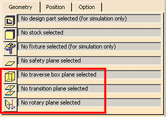
The Safety plane is not taken into account for the generation of transition paths.
When Generate Transition Paths
![]() is selected, the Transition Paths dialog box appears. You must select the
manufacturing program to be processed and set the desired options.
is selected, the Transition Paths dialog box appears. You must select the
manufacturing program to be processed and set the desired options.
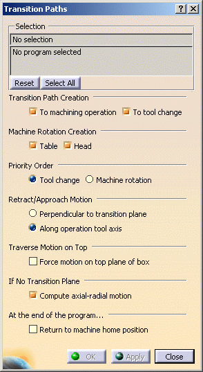
Transition Path Creation: specifies where transition paths are to be added in the program:
Machine Rotation Creation: allows creation of Rotary motion embedded in the transition path with:
Priority Order: specifies the preferred order between Tool Change and Machine Rotation when they are both present before a machining operation.
Retract/Approach Motion: specifies how retract and approach motions are to be done globally for all the transition paths of all selected programs:
If a specific retract or approach is required on a machining operation, it should be defined by macros on the operation.
Traverse Motion on Top: this
option is taken into account only when all 5 traverse planes are defined in the
Part Operation. It is useful when a transition path needs to go from one side
to the opposite side of the traverse box.
The intermediate plane can be any one of the three other planes.
If the check box is selected, then the top plane is used as the intermediate
plane.
Otherwise, the motion will be done using the intermediate plane that gives the
shortest path.
Compute axial-radial motion: if a traverse box is not defined and no transition plane is selected, selecting this check box authorizes 2.5 axis motion only. Tool axis direction at start and end of motion must be the same.
Return to machine home position: Generates an additional Transition Path after the last Machining Operation in order to return to the machine home position.
The general operation of Transition Path generation is outlined below. It assumes that an appropriate generic machine has been specified in the Part Operation.
If Table Rotation option is selected, and if a table rotation is needed, the tool retracts to the specified rotary plane and makes the table rotation. A head rotation is also done if necessary.
If Compute axial-radial motion is selected, the tool
approaches the next point in 2.5 axis motion.
Otherwise, the tool approaches the next point in linear motion.
For a transition path with table motion, the tool approaches the next point in
2.5 axis motion after the table rotation.
If Table Rotation option is not selected, or if a table rotation is not needed, the Transition Path capability checks whether or not a valid traverse box is defined.
If a valid traverse box is defined, the traverse box motion is computed. This motion may be modified according whenever valid transition planes are specified. A head rotation are also done if necessary.
If no valid traverse box is defined, the Transition Path capability verifies whether or not valid transition planes are defined.
If valid transition planes are defined, the tool retracts to these planes.
If no valid transition planes are defined, the Transition Path
capability verifies whether or not the Axial Radial option is selected.
If Compute axial-radial motion is selected, the tool
approaches the next point in 2.5 axis motion.
Otherwise, the tool approaches the next point in linear motion.
This is the case when a generic 5-axis machine is selected in the Part Operation.
The 5 traverse box planes defined on the Part operation delimit
a traverse box.
First, the transition path is computed by taken into account this traverse box.
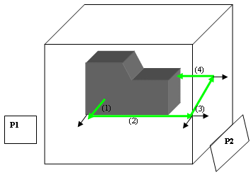
Retract and Approach motions are automatically defined.
The transitions motions are done in RAPID mode.
The Retract/Approach option can be set to define the motions type:
Perpendicular to transition plane (the tool axis of the machining operation is kept)
Along operation tool axis, until the transition plane.
Transition motions are done as follows:
1.Perpendicular retract (1) to the plane (with the same tool
axis of the operation) or retract along the tool axis
2.Transition motion (2) through the plane (P1) until the intersection of planes
(P1 and P2)
3.Tool axis modification
4.Transition motion (3) through the plane (P2) until the perpendicular (or
along the tool axis) of the next operation
5.Approach motion (4) to the next operation (tool axis of the operation)
Note that during transition motions the tool tip is on the traverse planes.
Then transition planes are used to modify these transition motions by reducing air cuts.
First, transition motions are done as follows (respecting the traverse box):
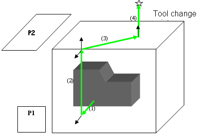
1. Perpendicular retract (1) to the plane (with the same tool
axis than the operation) or retract along the tool axis
2. Transition motion (2) through the plane (P1) until the intersection of
planes (P1 and P2)
3. Tool axis modification: Normal to the next plane (P2).
4. Transition motion (3) through the plane (P2) until the perpendicular of the
tool change
5. Approach motion (4) to the tool change
Then transition planes are used to modify these transition motions by reducing air cuts.
The transition path is done between the last point of the machining operation (last point of the retract macro) and the first point of the next machining operation (first point of the approach macro).
No control or cut of machining operation motions (including macro motions) is done outside the traverse box. The macro should be defined inside the traverse box. The transition paths are then generated up to the traverse box planes.
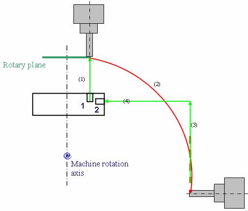
The rotary plane is taken into account in order to define a
safety distance.
The rotary plane must be parallel to the machine rotary axis. Thus, if the
machine as several rotary axis, several planes must be selected.
There are several cases:
None of the selected Rotary planes are parallel to the machine rotary axis: the furthest point between the rotary axis and the last point of the previous operation or the first point of the next operation defines the radius of the rotation.
Some of the selected Rotary planes are parallel to the machine rotary axis: the plane that defines the maximum distance with the rotary axis is taken into account.
The last point of the previous operation or the first point of the next operation is further from the machine rotation axis than all rotary planes: the rotary planes are not taken into account.
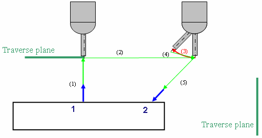
In the previous example, if machine head rotation generation is chosen, the transition path is computed the same way as for a 5 axis machine without generation of machine rotations. The tool tip path follows traverse box planes and transition planes. The difference is that for each modification of the tool axis, a machine head rotation is generated as well as tool motions take back the tool tip on the planes.
Example1:
The tool axes are different and the traverse planes are different: the head rotation is performed at the traverse plane intersection with the following behavior.
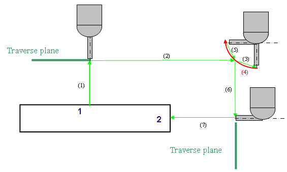
Example 2:
The tool axes are different, the traverse plane is the same: the head rotation is performed as follows.
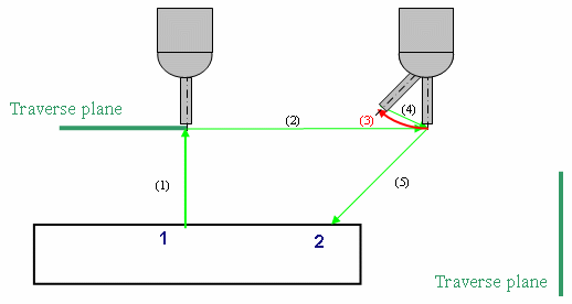
Example 3:
The machining operations are defined at opposite sides of the traverse box.
The transition motions are generated in 3 planes: then head rotations are done at the intersection of planes.
In this case, in the intermediate plane, the tool axis is defined as being perpendicular to the plane during transition motion in this plane.
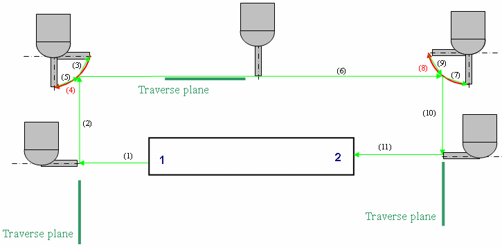
The transition planes are used to modify the transition motions respecting the traverse box plane by reducing air cuts.
Example:
A machining operation is defined at the bottom of the part.
Motion mode is set to Along operation tool axis.
A transition plane defines the bottom limit of the box.
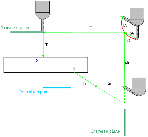
The behavior is the same as that described in Transition Between Operations.
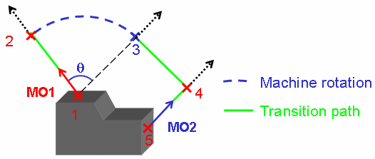
The tool path is a circular arc for table rotation and head
rotation.
Transition path needs to be computed before the computation of the machine
rotation tool path in order to have the start position (position 2 in the
figure below).
