This section deals with the following topics related to the APT output generated from the manufacturing program:
Syntax of APT instructions generated by Machining products is described below. Blank characters used for presentation comfort on file are not mentioned.
Example of format:
'AUTOPS'

  'INDIRV/',F11.5,',',F11.5,',',F11.5'

  'TLON,GOFWD/ (CIRCLE/',F13.5,',',F13.5,',',F13.5,',$',T73,'CIR',I5

  F13.5,'),ON,2,INTOF,$'

  '(LINE/',F13.5,',',F13.5,',',F13.5,',$'

  F13.5,',',F13.5,',',F13.5,')'
Example of generated APT source:
AUTOPS

  INDIRV/ 0.00000, -1.00000, 0.00000

  TLON,GOFWD/ (CIRCLE/ 0.00000, 0.00000, 0.00000,$ CIR 1

  50.00000),ON,2,INTOF,$

  (LINE/ 0.00000, 0.00000, 0.00000,$

  50.00000, 0.00000, 0.00000)
'$$',6X,'GENERATED ON ',A28,' AT ',A8 |
start of execution (date, time) |
'PPRINT OPERATION NUMBER: ',I4
|
operation order number in part operation |
A80 |
PP instruction string |
'$$*CATIA0' |
NC axis identifier (may be blank if table rotation operation). NC axis matrix definition in absolute axis (*axis1) |
'TLAXIS/'F9.6,2(',',F9.6) |
tool axis components expressed in machining axis system. |
'MULTAX/ON'
|
Manages the output format of GOTO statements in a 5-axis program
that mixes pure 5-axis operations and locked axis operations. (GOTO / X, Y, Z, I, J, K for pure 5-axis motions, and GOTO / X, Y, Z for locked axis motions). See MULTAX Influence on APT Source. |
'GOTO/',F11.5,2(',',F11.5),T73,'PT ',I5
|
tool tip coordinates, point number
tool tip coordinates, point number |
'CUTTER/',4(F10.6,','),F10.6,',$' |
cutter diameter, corner radius, distance center corner to tool axis, corner radius, 0.0, beta angle, height |
'CUTTER/',F10.6 |
nose radius |
'INTOL /',F11.5
|
machining tolerance
0.0 |
'FEDRAT/',F10.4
|
feedrate value
|
'GOTO/',F11.5,2(',',F11.5),T73,'PT ',I5
|
tool tip coordinates, point number
tool tip incremental move, point number |
'AUTOPS'
EITHER:
OR:
|
-
components of circle tangent at arc start pt circle center coords, circle number
radius, circle center coords,
radius, |
'PSIS/(PLANE/(POINT/',F11.5,2(',',F11.5),'),PERPTO,$'
|
tool tip coordinates, circle axis components components of tangent at arc start point circle center coords, circle number |
|
EITHER:
|
circle axis components, radius, circle center coordinates, circle axis components, circle center coordinates, arc end point coordinates |
|
OR:
|
circle axis components, radius, circle center coordinates, circle axis components, circle center coordinates, arc end point coordinates |
A MULTAX statement (MULTAX, MULTAX/ON, MULTAX/OFF) may be defined anywhere in the program (for example, in a PP word statement or a macro path).
MULTAX statements found during APT generation will influence the output format.
MULTAX statements are searched and identified in any PP word statement. If a MULTAX or MULTAX/ON statement is found, the following linear motions will be written with the format: GOTO/ X, Y, Z, I, J, K
If a MULTAX/OFF statement is found, the following linear motions
will be written GOTO/ X, Y, Z and the tool axis will be considered as locked.
The components of the locked tool axis are the components defined on the last
5-axis position preceding the MULTAX/OFF statement. Therefore, no TLAXIS statement
is generated after a MULTAX/OFF statement.
In a sequence of motions following a MULTAX/OFF statement, the tool axis orientation is checked, and as soon as it is not constant, a MULTAX/ON statement will be added, possibly with a warning message in the log file.
Example of APT source:
...

    PPRINT OPERATION NAME : Tool Change

    PPRINT Start generation of : Tool Change

    MULTAX/ON

    GOTO / 0.00000, 27.16535, 20.47244, 0.000000, 0.000000, 1.000000

    $$ TOOLCHANGEBEGINNING

    CUTTER/ 1.259843, 0.000000, 0.629921, 0.000000, 0.000000,$

    0.000000, 0.984250

    $$ TOOLCHANGEEND

    PPRINT End of generation of : Tool Change

    ...

    MULTAX/OFF

    ...

    RAPID

    GOTO / 7.29167, 15.48687, 16.10080

    RAPID

    GOTO / 7.29167, 15.48687, 15.13780

    ...

    MULTAX/ON

    ...

    RAPID

    GOTO / 2.74137, 14.56693, 16.10080, 0.000000, 0.000000, 1.000000

    RAPID

    GOTO / 2.74137, 14.56693, 15.13780, 0.000000, 0.000000, 1.000000

    ...
Note that the behavior previous to Release 12 was that MULTAX statements had no influence on the format of GOTO statements.
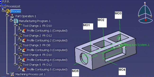
The tool change point is specified on the Part Operation and the
tool axis at this point is determined by the spindle orientation (I, J, K) on
the machine.
In the particular case where no machine is defined on the Part Operation, this
tool axis is determined by the z-axis of the Part Operation's machining axis system.
Tool Axis statement (TLAXIS) is always output for the first Tool Change.
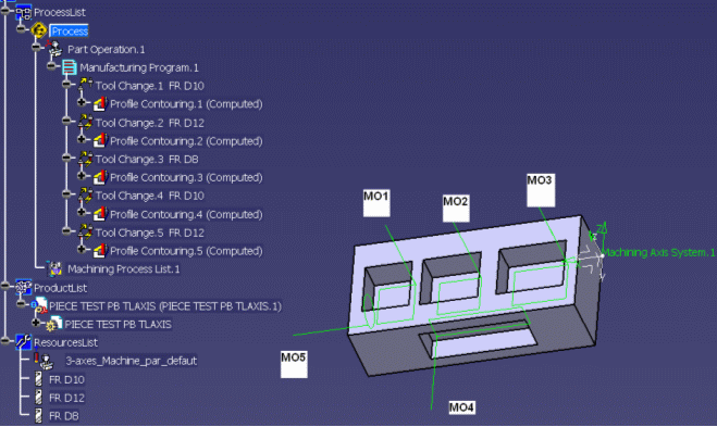
For the following Tool Changes, the tool axis of the previous machining operation is taken into account. If it is different from Tool Change position defined on the setup then a TLAXIS statement is output for that Tool Change.
Example 1

If the tool axis at the Tool Change position is (0,0,1), then a TLAXIS/ 0.000000, 0.000000, 1.000000 statement is output for the first and fifth Tool Changes.
$$ OPERATION NAME : Tool Change.1

    TLAXIS/ 0.000000, 0.000000, 1.000000

    etc

    $$ Start generation of : Profile Contouring.1

    etc

    $$ Start generation of : Tool Change.2

    etc

    $$ Start generation of : Profile Contouring.2

    etc

    $$ OPERATION NAME : Tool Change.3

    etc

    $$ Start generation of : Tool Change.3

    etc

    $$ Start generation of : Profile Contouring.3

    etc

    $$ Start generation of : Tool Change.4

    etc

    $$ Start generation of : Profile Contouring.4

    TLAXIS/ 0.000000, 1.000000, 0.000000

    etc

    $$ Start generation of : Tool Change.5

    TLAXIS/ 0.000000, 0.000000, 1.000000

    etc

    $$ Start generation of : Profile Contouring.5

    TLAXIS/ 1.000000, 0.000000, 0.000000
Example 2

If the tool axis at the Tool Change position is (0,0,1) and the tool axes of all the machining operations are different from the Tool Change position axis, then a TLAXIS/ 0.000000, 0.000000, 1.000000 statement is output for all the Tool Changes.
$$ Start generation of : Tool Change.1

    TLAXIS/ 0.000000, 0.000000, 1.000000

    etc

    $$ Start generation of : Profile Contouring.1

    TLAXIS/ 0.000000, 1.000000, 0.000000

    etc

    $$ Start generation of : Tool Change.2

    TLAXIS/ 0.000000, 0.000000, 1.000000

    etc

    $$ Start generation of : Profile Contouring.2

    TLAXIS/ 0.000000, 1.000000, 0.000000

    etc

    $$ Start generation of : Tool Change.3

    TLAXIS/ 0.000000, 0.000000, 1.000000

    etc

    $$ Start generation of : Profile Contouring.3

    TLAXIS/ 0.000000, 1.000000, 0.000000

    etc

    $$ Start generation of : Tool Change.4

    TLAXIS/ 0.000000, 0.000000, 1.000000

    etc

    $$ Start generation of : Profile Contouring.4

    TLAXIS/ 0.000000, 0.000000,-1.000000

    etc

    $$ Start generation of : Tool Change.5

    TLAXIS/ 0.000000, 0.000000, 1.000000

    etc

    $$ Start generation of : Profile Contouring.5

    TLAXIS/ 1.000000, 0.000000, 0.000000
According to APT standard formats, all feedrate statements (except RAPID) are modal. This means that they are applied on all following points until next the feedrate statement.
However, the RAPID instruction is not modal. This means that the RAPID statement is applied only on the next GOTO motion. For example in a linking macro with rapid feedrate, a RAPID instruction is written before each of the three GOTO points of the macro.
Another APT standard format rule that is specific to the RAPID word, is to not repeat unnecessarily the current machining feedrate after the last point in RAPID. The machining feedrate will be applied natively.
In the example below, rapid feedrate only applies to the first GOTO point. The machining feedrate that was current before the RAPID statement applies to the second GOTO point:
FEDRAT/ 300.0000,MMPM

    GOTO / -69.00000, 40.00000, 46.00000

    GOTO / -69.00000, 50.00000, 0.00000
RAPID

    GOTO / -80.0000, -23.0000, 16.0000

    GOTO / -90.0000, -21.0000, 16.0000
In the APT language, the way to describe a circle is ambiguous near 180deg
and 360deg.
So, in some specific cases, the circle must be split in two.
Prior to R15, angles of the circular motions of the tool path were between
0 and 180deg.
The MFG_BATCH_SPLIT_CIRCLE variable could be used to split circles
into two circles of half the angle, if angle was greater than 179deg.
Since R15, new generated tool paths can have circular motions with an angle
lying between 0 and 360deg. So, the output file is not always the same as the
prior to R15 behavior.
For example, four 90deg circles are now stored in a single 360deg circle.
If the MFG_BATCH_SPLIT_CIRCLE variable is used, it splits the circles
into two half-circles. However, this is not always appropriate for angles greater
than 180deg.
Another variable MFG_BATCH_SPLIT_CIRCLE_V4 should be used to split
circles in releases since R15.
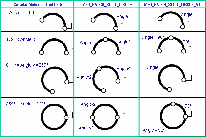
With this variable, a circle with an angle (A) between 179deg and 181deg or between
359deg and 360deg is split into two circles. The first has an angle of 90deg and
the second has an angle of (A – 90deg).
This is identical to CATIA V4 behavior.
Note: If no variable is used, the circle is not split.
Examples of this are illustrated below (the arrow indicates the start of motion):

For additional information, see MfgBatch Utility for Generating NC Data (*SPC keyword).