This document provides methodology for machining symmetrical parts and left-hand/right-hand parts. A user task showing you how to program using Opposite Hand Machining techniques is also include in this guide.
Although this is quite a flexible process, there are usually 3 steps involved:
By following this method, you will obtain a program for the symmetrical part that has the same cutting conditions as the initial part.
The following methodology assumes that a proven program already exists for one symmetrical half of a part or for one workpiece in a left-hand/right-hand pair.
Taking the example of an existing left-hand program, you should make a copy of the program (or the operations in the program) in one of the following ways:
To transform the copied program (or operations):
After applying the transformation to the tool path, the cutting conditions of some operations may be reversed (climb/conventional milling, for example).
Modified operations can be easily identified in the program due to the
update symbols (![]() ) that appear
in the tree. The tool paths of these operations must be computed or
re-computed.
) that appear
in the tree. The tool paths of these operations must be computed or
re-computed.
Due to the applied transformation followed by the Reverse Machining Conditions processing, the cutting conditions are now reset to the values of the initial program. A summary of the processing appears on an information pop-up.
Note that the cutting conditions of deactivated operations (![]() )
can be changed, since they can be edited. However, the cutting conditions of
locked operations (
)
can be changed, since they can be edited. However, the cutting conditions of
locked operations (![]() ) cannot be
changed, since they cannot be edited.
) cannot be
changed, since they cannot be edited.
The program may need to be finalized by means of some local editing.
If the operations of the original program are linked one after the other, you may need to reverse the order of these operations in the processed program. This is the case, for example, if the end point of Operation1 is the start point of Operation2.
In this case, you can use the Reorder Operations List command
![]() to reverse the order
of one or more groups of operations. In the example below, the groups A, B, C
and E, F were selected and reversed.
to reverse the order
of one or more groups of operations. In the example below, the groups A, B, C
and E, F were selected and reversed.
| Operation.A Operation.B Operation.C |
---------------> |
Operation.C Operation.B Operation.A |
| Operation.D | Operation.D | |
| Operation.E Operation.F |
Operation.F Operation.E |
Note that groups of operations must be selected one after the other in the tree and they must use the same tool. Operations in each group must be selected from top to bottom.
Similarly, it may be necessary to inverse the approach and retract macros on
an operation. In this case, select the relevant operations and select the
Inverse Macros command
![]() .
.
The following table summarizes the references elements that are transformed by Opposite Hand Machining. Typically, the Reverse Machining Conditions command must be applied to these operations in order to retrieve the cutting conditions of the initial program.
| Operation | Effect of Opposite Hand Machining |
| 3-axis Roughing | Climb and Conventional options are inverted. |
| Spiral Milling | Climb and Conventional options are inverted. |
| Axial Machining Operations | Order of pattern points is reversed in the tool path. |
| Pocketing | Climb and Conventional options are inverted. |
| Facing | Climb and Conventional options are inverted. |
| Profile Contouring | Climb and Conventional options are inverted. Order of multi-contour is inverted. Start and End elements, offsets, and conditions are inverted. |
| Groove Milling | Climb and Conventional options are inverted. |
| 3-axis/5-axis Isoparametric Machining | Order of parts is inverted. Corners 1 and 2 are swapped. Corners 3 and 4 are swapped. Corresponding interpolation axes at corners are swapped. |
| 5-axis Flank Contouring | Order of drives is inverted as follows when
the Close tool path check box is not selected in the operation's
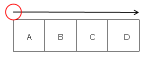
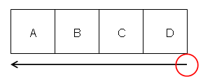
Machining parameters tab. Drives A, B, C, D are machined in the order D, C, B, A. Before Opposite Hand Machining:
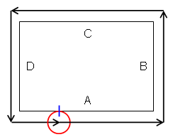
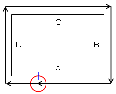
Order of drives is inverted as follows when the Close tool path
check box is selected in the operation's Machining parameters tab. Before Opposite Hand Machining:
Start and End elements, offsets, and conditions are inverted. |
| 5-axis Curve Machining | Climb and Conventional options are inverted. Sign of Tilt angle is changed to invert the left/right condition. Couple of Points limit elements are swapped. For Tangent Axis guidance
along isoparametric lines: |
| CUTCOM | You should check that the desired cutter compensation is still applied (correct side, and so on). |
Machining of any symmetrical right part, when left part machining is already
defined.
The right part does not exist as a physical model, everything is referenced on
the left part.
Program of left-hand part has been defined.
Operations in left-hand program have been updated because of design changes, but the tool path was fully associative.
In this case, right-hand program is updated and is associative.
Operations in left-hand program have been updated because of design changes, some operations have been edited to take new geometry into account.
Some operations' options in left-hand program have been modified, or some operations have been added to left part.