 |
This task shows how
to apply a TRACUT Operator to a delimited sequence of operations in the
program.
The sequence is delimited by TRACUT-TRACUT/NOMORE type instructions. |
 |
Open the
CopyTransfoSample.CATPart document. |
 |
1. |
Create a first Pocketing operation on the first square
cut-out. Create a second Pocketing operation using a different tool on the
first triangular cut-out. To create these pockets, make sure that the
Island Detection contextual command is not active before
you define the pocket bottom. |
| |
2. |
Right-click the Manufacturing Program and select the
Compute Tool Path contextual menu. Select the Compute if
necessary option in the pop-up that appears. |
|
3. |
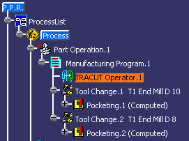
Select Tool Change.1 in the program. Select TRACUT
Operator
 in the
Auxiliary Operations toolbar (Transformation
Management Sub-toolbar). in the
Auxiliary Operations toolbar (Transformation
Management Sub-toolbar).
A TRACUT Operator is inserted in the program before Tool Change.1 and
the TRACUT Operator dialog box appears.
 |
|
4. |
Select
 (Create
a TRACUT/NOMORE instruction) in the dialog box to create a TRACUT/NOMORE
instruction. (Create
a TRACUT/NOMORE instruction) in the dialog box to create a TRACUT/NOMORE
instruction.
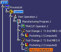
Select an entity in the program to specify the insertion level.
In this scenario, select Pocketing.2 to insert the TRACUT/NOMORE
instruction after that operation.

The TRACUT Operator will apply to the two tool changes and the two
pocketing operations. |
|
5. |
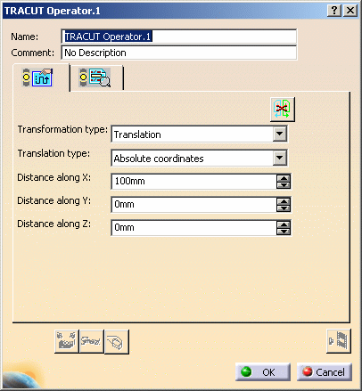
Set the Transformation type to
Translation.
Choose the Translation type to Absolute Coordinates.
Specify the translation by setting the Distance along X to
-100mm.
|
| |
6. |
If needed, select the Syntax tab
 to consult the
syntax that will be applied for the TRACUT operator. to consult the
syntax that will be applied for the TRACUT operator. |
|
7. |
Click OK to create the TRACUT Operator in the program. |
|
8. |
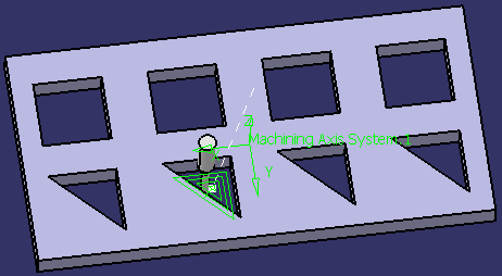
To visualize the tool path resulting from the defined
TRACUT Operator, select the first tool change in the program then click the
Replay Tool Path
 . .
Make sure that the TRACUT display mode is active in the Tool Path Replay
dialog box.
Replay the tool changes and pocketing operations.

Close the dialog box at the end of the replay. |
| |
More About Inserting a TRACUT Operator
The possible transformation types are as follows.
- Translation: choose the desired translation type then
specify the translation by:
- either giving X, Y, Z components in the absolute or the current
machining axis system
- or clicking the
Direction area to select a linear
geometric element for the direction and giving a length.
- Rotation: click the
Axis area to select a
linear geometric element as the axis of rotation then give a rotation
angle. If a circular edge is selected, the normal axis of the circle is
used.
- Mirror: click the
Mirror area to select a
planar geometric element as the axis of symmetry.
- Axis to axis: click the
From area to select a
first machining axis system then the To area to select a
second machining axis system. The first axis system will be transformed
into the second axis system.
- Affinity: select a machining axis system and define 3
scale factors to be applied along each of its axes: x,y,z. The
transformation matrix in the selected machining axis system will be:

- Scale: select a planar surface or a point and a scale
factor to be applied along the normal projection on the selected element.
- Matrix: This transformation will be defined by the matrix
definition of the transformation in the absolute axis system, the current
machining axis system, or a selected machining axis system.
In case of definition of the matrix in the absolute axis system or in
the current machining axis system, the matrix of the transformation is
stored in the model in the absolute axis system (it is invariant in this
axis system).
Choosing one or the other mode only changes the display of the
coordinates of the matrix.
Out of a current machining axis system context, the absolute axis system
will be used to display the matrix.
In case of definition of the matrix in a selected machining axis
system, the matrix of the transformation is stored relatively to this
selected machining axis system.
Status Management
TRACUT Operator will show an Exclamation symbol
 in standard cases: in standard cases:
- a reference geometry has been deleted.
TRACUT Operator will show an Update symbol
 in standard cases: in standard cases:
- reference geometry has been modified
- a parameter has been modified.
|
|
 |