For more information on this topic please refer to Design Changes and Associativity Mechanisms.
All the tabs of the Profile Contouring dialog box display a green status.
The Profile Contouring entity is displayed in the tree with no related symbol.
The
Profile Contouring entity is now displayed in the tree with an Update
symbol ![]() .
.
The Geometry tab has an orange status, indicating that the geometry has been modified.
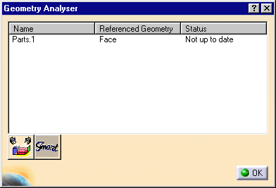
The Geometry Analyzer dialog box appears showing the status of the referenced geometry.
Geometry highlighted in this way helps you to analyze the design change.
You should check that there is no longer an Update symbol beside the Profile Contouring entity in the graph.
How to Analyze and Remove Geometry
You can analyze and, if needed, remove the geometry specified on a Machining Operation.
In the Machining Operation editor, three icon commands appear at the bottom of the Strategy, Geometry, and Macros tab pages. They provide capability to:
- preview the geometry specified by means of the current tab page
- preview the smart geometry by means of the current tab page
- remove the geometry specified by means of the current tab page.
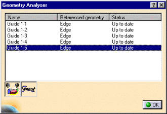
To analyze one geometry aggregate (guiding element, for example), right-click the corresponding sensitive area of the Machining Operation editor and select the Analyze contextual command. The Geometry Analyser dialog box appears.
- preview the geometry corresponding to the rows selected in the dialog box
- preview the smart geometry corresponding to the rows selected in the dialog box
- remove the geometry corresponding to the rows selected in the dialog box. You can easily remove unwanted or unused geometry (short lines that were automatically inserted in guides, for example).
The second column lists the names of the referenced geometries: Edge, Face, and so on.
The third column lists the geometry status: Up to date, Not up to date, or Not found.
The columns of the Geometry Analyser dialog box can be sorted by clicking on the column header. Multi-selection is possible .
![]()

