Make sure the front view is active. If not, double-click to activate it. Create a right projection view from the existing front view.
In the Visualization toolbar, activate the
Cutting Plane
![]() and the Display Backgrounds as Specified for Each View
and the Display Backgrounds as Specified for Each View
![]() icons.
icons.
-
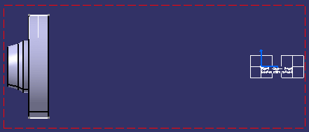
Double-click the right view to activate it.
-
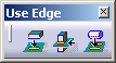
Click the Project 3D Silhouette Edges icon
 in the 3D Geometry toolbar (Use-edge sub-toolbar).
-
In the 3D background of the section view, select the canonical surface to be projected.
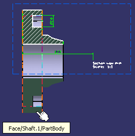
The silhouette edge is projected onto the right view plane.
-
Optionally, deactivate the Display Backgrounds as Specified for Each View
 icon to view the projected silhouette edge without the 3D background.
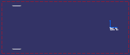
More about projecting 3D silhouette edges
When projecting 3D silhouette edges, remember the following points:
- You can only project a silhouette edge from a canonical surface (cylinder, sphere, torus) whose axis is parallel to the view plane.
- The projected geometry is created in the current view.
- If the selected element is invalid, an error message is displayed.
![]()