Numerics |
||
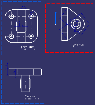
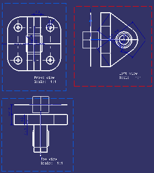
| 2D background | The visualization - in transparency - in the 2D window (through a design view) of the 3D representation of 2D elements which do not belong to the current view, but to other views. | |
| Below is an example of views with no 2D background: | ||
 |
||
| Below is an example of the same views with a 2D background: | ||
 |
||
| 2D component | A re-usable set of geometry and annotations, stored in a detail sheet or a catalog. A 2D component can be instantiated in any view. | |
| 2D window | A standard window with a specification tree and a 3D viewer that cannot be rotated. It is in this window that you create your layout, that is the views containing 2D geometry, dimensions, annotations and so on. | |
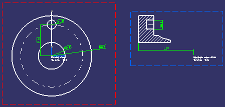
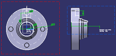
| 3D background | The visualization - in transparency - in the 2D window (through a design view or an isometric view) of all 3D elements. This includes edges, faces and 3D wireframe. | |
| Below is an example of views with no 3D background: | ||
 |
||
|
Below is an example of the same views with a 3D background: |
||
 |
||
| 3D window | A standard window with a specification tree and a 3D viewer that can be rotated. This window contains the 3D representation of a layout. | |
| 3D workbench | A workbench dedicated to the 3D edition of part or product documents, such as the Part Design or Product Structure workbench. | |
|
|
||
B |
||
| background view | In a sheet, the background view is dedicated to frames and title blocks. See also main view. | |
D |
||
| design view | A view in which you design and whose content can be
visualized and output in 3D context.
Design views have a specific position in 3D space. The 2D
background and the 3D background can be seen through design views.
Design views can be of the following types: Front, Left, Right, Rear, Top, Bottom, Auxiliary, Section and Section Cut. See also Isometric view. |
|
| detail sheet | A sheet that is used as an intermediate catalog for positioning 2D reference elements (geometry) that will be instantiated afterwards. A layout detail sheet contains a main view and a background view. | |
| display filter | A view filter which defines a list of elements to display and possibly overload while the remainder of the background is hidden. See also Mask filter. | |
| dress-up view | A view visualized only in the 2D Layout for 3D Design
workbench. No background (whether 2D or 3D) can be seen through such a
view. Dress-up views can be of the following types: main, background and views in detail sheets. |
|
E |
||
| equivalent filter | A 2D layout filter associative with a FTA capture and whose content corresponds to the objects shown or hidden in this capture. It is not possible to create an equivalent filter without creating a 2D layout from an FTA capture. This mask filter is not editable. | |
F |
||
| filter | See View filter. | |
I |
||
| isometric view | A type of view visualized only in the 2D Layout for 3D
Design workbench (not in a 3D window). However, the 3D background (as well
as the 2D background) can be seen through isometric views.
Note that isometric views are not design views. For this reason, a number of functionalities available for design views (such as creating use-edges, 3D profiles or 3D planes) are not available for isometric views. See also Design view. |
|
L |
||
| layout | A layout is represented in 2 different ways:
|
|
M |
||
| main view | In a sheet, the main view (also called working view) supports the geometry directly created in the sheet. See also background view. | |
| mask filter | A view filter which defines a list of elements to overload while the remainder of the background is displayed in the same way as defined in 3D. See also Display filter. | |
P |
||
| part layout | A layout which is stored in a part document. | |
| primary view | A primary view is the first basic view chosen to describe
an object because it best represents the shape of this object. The primary
view also determines the projection views' position in the sheet.
|
|
| projection view | A view conceived to be drawn or projected onto planes known as projection planes. | |
S |
||
| sheet | A set of views. In the 2D Layout for 3D Design workbench, a sheet contains a main view and a background view. It can also contain design views and isometric views. | |
U |
||
| use-edge | A datum element that results from one of the following operations: projection of a 3D element, intersection of a 3D element or projection of 3D silhouette edges. Note that use-edges in the 2D Layout for 3D Design workbench are not associative to the reference element. | |
V |
||
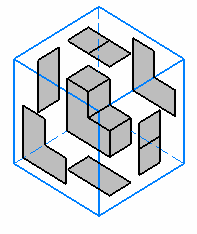
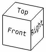
| view box | In the 3D space, the projection views of a layout can be
seen as a box (or a cube) containing the part to be designed. This cube is
made of basic views: Front, Left, Right, Top, Bottom and Rear. A view box gathers all the data needed to fully define the layout of a view set in the 2D window, as well as the position of each view in the 3D space. |
|
 |
 |
|
| view content | All 2D elements aggregated under a given view. | |
| view filter | View filters modify the visualization of some elements that are represented in the background of layout views. They allow users to overload global graphic properties, thus making some background elements invisible, unpickable or low-intensified. See also Display filter and Mask filter. | |
| view plane definition | Corresponds to the specific position of design views in the 3D space. | |
| view set | Corresponds to the set of views which have been created from a primary view, that is the primary view, its related basic views, as well as any isometric view, section view, section cut and/or auxiliary view created from any view belonging to the view set. | |