|
|
This task
illustrates how to create turning operations to machine large diameter
holes on a milling center machine equipped with a facing head and rotary
table. This is made possible by specifying local planes for turning at
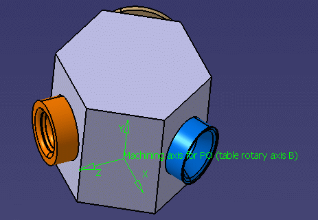
machining operation level. The facing head is a mechanism mounted on the head of the milling center to support lathe tools. This configuration can be used to machine large diameter holes with better quality than milling. In this scenario, the three large holes to be machined are located in different turning planes around the table rotary axis (C).
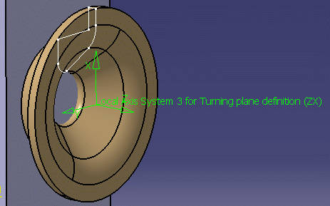
Each turning plane is defined by two axes (ZX) of a local machining axis system, so that each hole can be reached by rotating the table.
The tool mounted on the facing head is piloted along the U-axis to machine along the profile of the hole. |
||
|
|
Open the
TurningOperationOnMillMachine.CATProcess document, then select
Machining > Lathe Machining from the Start menu.
|
||
|
|
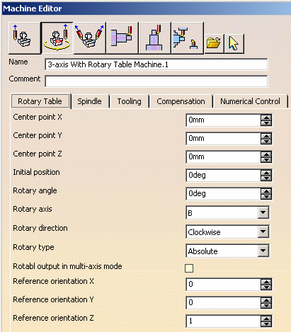
1. | Double-click the Part Operation
and access the Machine editor. A 3-axis rotary table machine is already
selected. Make the following settings in the Rotary Table tab.
|
|
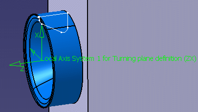
| 2. | Select the Machining Axis Change
icon Position the origin of the axis by selecting the outer circle of the hole. The axis origin will be positioned at the hole center. Set the orientation of the X-axis (radial) and Z-axis (axial) by using
one of the proposed methods (Selection or Manual Components, for
example).
|
||
| 3. | Select the Profile Finish
Turning icon
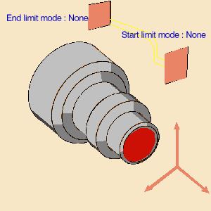
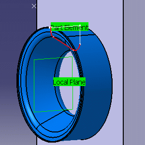
Use the Geometry tab to:
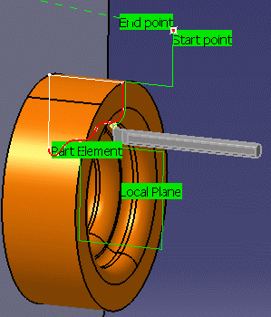
Use the Macro tab to define an approach macro by selecting a start point and a retract macro by selecting an end point. |
||
 |
 |
||
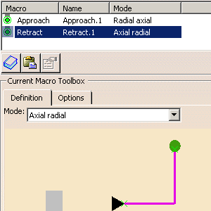
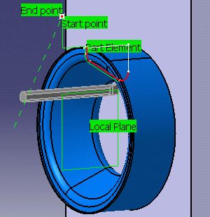
| Use the Macro tab to define an
approach macro by selecting a start point and a retract macro by
selecting an end point. Check the tool path by means of a replay. |
|||
 |
 |
||
| 4. | Repeat the steps above to create a local machining axis and a Profile Finish Turning operation for the other two holes. | ||
 |
 |
||
| 5. | When the three turning
operations are computed your program should look something like this:
|
||
|
|
Please note the following
points. They are dealt with in more detail in the
Methodology section.
|
||
|
|
|||
