Automatic switch to Design mode:
If you work with the cache system in visualization mode, you no longer need to use Edit > Representations > Design Mode beforehand as the switch to design mode is automatic (an eye appears as you point the product in the geometry or specification tree). All you need to do is click on the object.
-
Click Gear Joint
 in the Kinematics Joints toolbar or select Insert > New
Joint > Gear... from the Menu bar. The Joint Creation: Gear
dialog box appears.
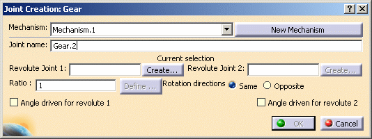
The Mechanism is identified in the specification tree. Now you need to select two Revolute joints. -
Select Revolute.1 either in the specification tree or in the geometry area.
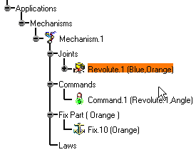
-
Create Revolute.2 within the Gear command. For this: click
 .The Joint
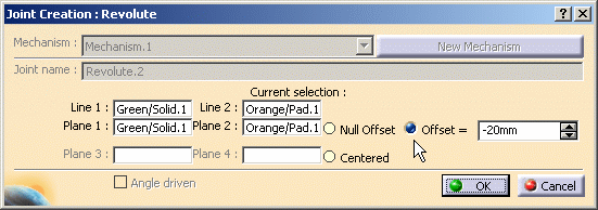
Creation: Revolute dialog box appears automatically:
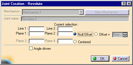
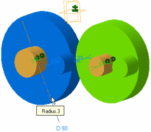
Select line .1 (green cylinder axis) and line.2 (orange cylinder axis) as shown below in the geometry area: 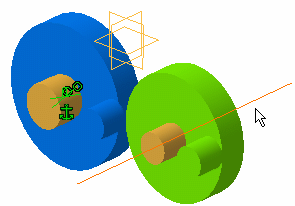
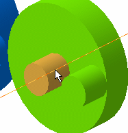
Select plane.1 (green cylinder face) and plane.2 (orange cylinder face) either in the specification tree or in the geometry area: 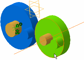
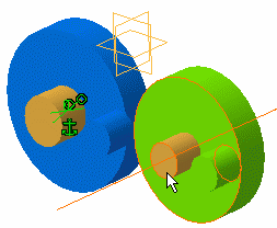
-
Select the Offset option button and keep the default value. When done, click Ok.
-
Assign a command, select for instance the Angle driven for revolute1 check box.
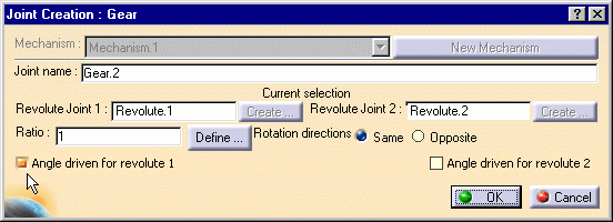
About Ratio definition
Two methods are available to define the ratio parameter:
-
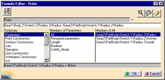
modifying the formula (in this case the ratio is a knowledge parameter)
for this, right-click in the ratio field and use the Edit Formula contextual menu displayed

- using the Define option in the joint creation dialog box to calculate the ratio automatically
-
-
Click
 to define the ratio
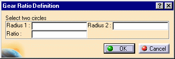
parameter automatically. The Gear Ratio Definition dialog box
is automatically displayed.
-
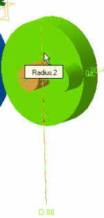
Select the two circles in the geometry area.

-
Click Ok when done
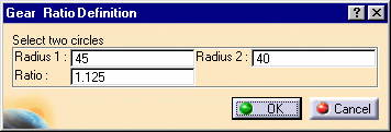
The calculated ratio appears in the Joint Creation: Gear dialog box
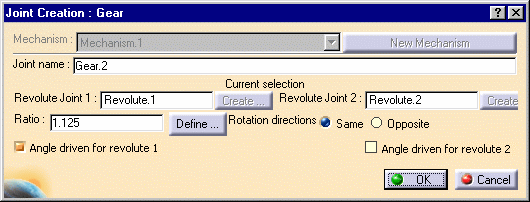
-
Change the rotation direction option if needed.
The default is Same (positive)
Opposite is negative
Note: simulate your mechanism with commands to check the direction is the one you want
-
Click Ok when done
-
Click Ok when done. The ratio is updated
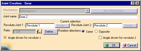
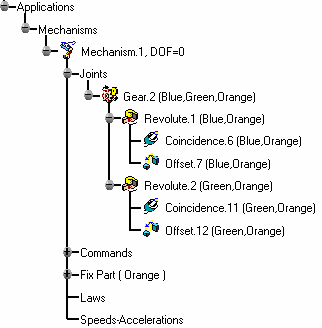
The gear joint is created and identified in the specification tree.
Now expand the gear joint you have just created, the embedded leaf joints are displayed.Note: the joints involved in a compound joint can be neither edited nor deleted directly.
-
Open the GearV5_Result.CATProduct to check your result

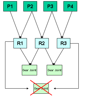
Note: To create a gear joint, the two revolute joints involved in the gear joint must rely on a same support part.
See picture below: (P stands for Part, R for Revolute)
![]()
