![]()
Open the Edit_SlideCurve.CATProduct document.
![]()
When you create joints, you can define the mechanism within the same dialog box. Remember though, that you create a mechanism independently from the joints by selecting Insert >New Mechanism... from the menu bar.
Automatic switch to Design mode:
If you work with the cache system in visualization mode, you no longer need to use Edit > Representations >Design Mode beforehand as the switch to design mode is automatic (an eye appears as you point the product in the geometry or specification tree). All you need to do is click.
-
Check the mechanism can be simulated, for this: click Simulation with Commands
 in the Simulation toolbar
The Kinematics Simulation dialog box appears.
The command of the kinematics mechanism is available as shown below.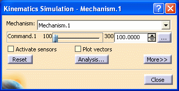

Note: the state of the dialog box depends on your settings (expanded or not)
-
Run your simulation using the slider of the command.
-
Click the
 button and when done, click Close.
 -
In the specification tree, double-click the joint to be modified.
In our example, double-click Joint.1The Joint Edition dialog box is displayed:
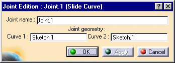
-
In the Joint Edition: Joint.1 dialog box, select the curve you want to be replaced
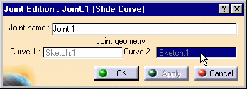
The geometry involved in the slide curve joint is low-lighted.
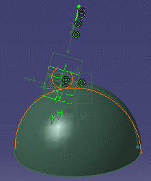
-
Select a new curve for your slide curve joint in the geometry area.

-
Click Apply to check the new joint. The mechanism parts are automatically reassembled accordingly.
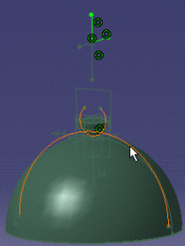
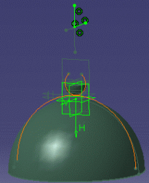
-
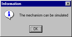
Click OK to confirm you operation. The mechanism can be simulated, an information message is displayed:
![]()
For more information, refer to About Joints and Creating Mechanisms and Joints.
![]()