![]()
This task shows how to edit point curve joints in a V5 mechanism modifying the elements involved in the joint position
![]()
Open the Edit_PointCurve.CATProduct document.
![]()
Automatic switch to Design mode:
If you work with the cache system in visualization mode,
you no longer need to use Edit > Representations > Design Mode
beforehand as the switch to design mode is automatic (an eye appears as you
point the product in the geometry or specification tree). All you need to
do is click on the object.
-
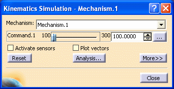
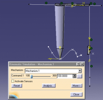
Check the mechanism can be simulated, for this: click Simulation with Commands
 .
.The Kinematics Simulation dialog box appears:
Note: the state of the dialog box depends on your settings (expanded or collapsed)
The command of the kinematics mechanism is available as shown below.
-
Run your simulation using the slider of the command.
-
Click the
 button and when done, click Close.
 -
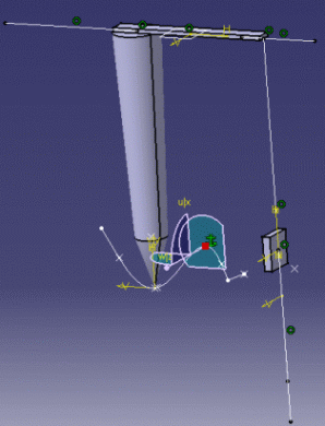
Modify the geometry position: in our example, you are going to move the curve.Right-click the 3D compass and select Snap Automatically to Selected Object item from the contextual menu displayed:

-
Select the curve either in the specification tree or in the geometry area. The 3D compass is automatically snapped onto the curve object
-
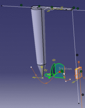
Drag the compass as shown below:
-
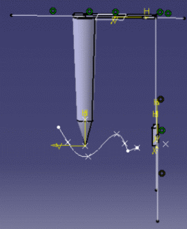
Detach the 3D compass:
-
Click Simulation with Commands again
.
The mechanism can no longer be simulated. A warning message is displayed
(it is not always the case as sometimes, DMU Kinematics Simulator
performs an automatic update).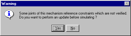
-
Click Yes. The Mechanism is updated automatically:
-
the parts involved in the mechanism are reassembled
-
the mechanism can be simulated
The Kinematics Simulation dialog box appears:
-
![]()
For more information, refer to About Joints and Creating Mechanisms and Joints.
![]()