![]()
This task shows how to create joints in a V5 mechanism.
You can now create 16 joint types from the following list:
-
Revolute

-
Prismatic

-
Cylindrical

-
Spherical

-
Universal

These joint can now be created using axis systems. See Creating Axis-based Joints
-
Planar

-
Rigid

-
Gear

-
Cable

-
Rack

-
Roll Curve

-
Slide Curve

-
Point Curve

-
Point Surface

-
CV

-
Screw

![]()
Open the
rods+3joints.CATProduct document.
![]()
When you create joints, you can define the mechanism within the same dialog box. Remember, you can also create a mechanism independently from the joints by selecting Insert New Mechanism... from the menu bar.
-
Click Revolute Joint in the DMU Kinematics toolbar.
-
Click the arrow within the icon to undock the Kinematics Joints toolbar.

The Kinematics Joints toolbar is displayed:

-
Select the joint type of your choice.
-
For instance click Rigid Joint
 .The
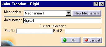
Joint Creation: Rigid dialog box is displayed:

The term Rigid corresponds to Fully restricted in the standard Kinematics terminology.
-
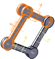
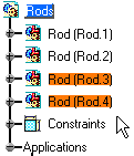
Select the parts either in the geometry area or in the specification tree.


-
Click Ok to confirm your operation.
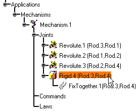
The rigid joint you have just created, is identified in the specification tree.

![]()
For more information, refer to About Joints and Creating Mechanisms and Joints.
![]()