Applying a Save As Model operation on a Volume or a Surface means that the model keeps in memory the path of the Part and you can resynchronize the model after modifying the Part.
Now, you can launch the associative mode whatever the CATIA components' nature is (volumic or not). Therefore, a non-associative Save as Model can be applied on non-volumic or non-surfacic elements. These elements are migrated but there is no link between the migrated components and the CATPart. In fact, they are recreated in the V4 model.
How to create a model in associative mode with the Batch migration
CATV5ToV4 -if input Part -of output model -mod ASSO
-if : specify the CATPart to be processed
-of : output directory in non-associative mode or explicit model
-
Creation of the model in associative mode:
Both types of elements (associative and non-associative) are created into the geometrical set:
-
migration in associative mode for Solids, Wireframes and Surfaces.
These V4 elements, which are migrated in the Associative mode, keep a link with the CATPart.
For the two dimension elements (Surface elements), this link leads to restrictions in CATIA V4. To erase them in V4, it is necessary to destroy this link. -
non-associative migration for all the other types of geometrical elements (called non-associative elements): pints, lines, curves, faces.
-
-
Synchronization of the model:
The Following actions are operated:
-
migration of the non-associative elements of the current CATPart document into the geometrical Set
-
moving of the previous non-associative elements into a layer called " bin " layer
-
synchronization of the associative elements (2D: Surfaces; 3D:Volumes) on the current geometry of the CATPart.
At each stage of synchronization, the non-associative elements created during the previous migration are added in the "bin" layer. The non-associative elements of the current CATPart's geometry are entirely re-created.
In this way, the user, if he wants, can delete all the old non-associative geometry by selecting the "bin" layer in CATIA V4.
-
The Associative Mode offers better performances because only the last modifications are recalculated, which is not the case with the Non-Associative Mode.
The size of the generated models is different if you choose one mode or the other:
- with the Associative mode, the sub-elements are not migrated because a link is kept with the CATPart. Therefore, the size of the model is less important.
- with the Non-Associative mode, the resulting model is bigger because the historical data (building elements) are recreated in V5.
-
Number of the layer for non-associative data:
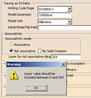
The number of layer can be specified by the user thanks to the Tools > Option > Compatibility Settings. Note that in V4 model, a number of layer can have a value between 0 and 254. If this setting is not informed, a default layer number is used: layer number 254. If you enter 255 for instance, a warning is displayed.
The layer is visible in the model. The user can put it in the No Show space or delete it if he wants.
-
Identifiers of the non-associative elements:
During the stage of synchronization, non-associative elements issued from the previous migration are moved into the "bin" layer and their identifiers are modified in order to know which migration number they come from. Each identifier is modified in that way: RxxxIDENT, where xxx is the migration number.
For instance, the identifier LINE.1 becomes R001LINE.1 at the first synchronization of the model. If we make two synchronizations, the model contains LINE.1 and the following identifiers R001LINE.1 and R002LINE.1.
How to create a model in associative mode interactively
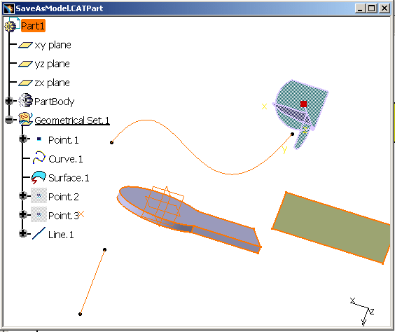 |
This CATPart contains:
|
-
Select the Associative mode in the Tools > Options > Compatibility Settings.

This option is kept in memory; if you reopen CATIA V5, the Associative Mode will be the active mode. -
Save the CATPart As a Model:
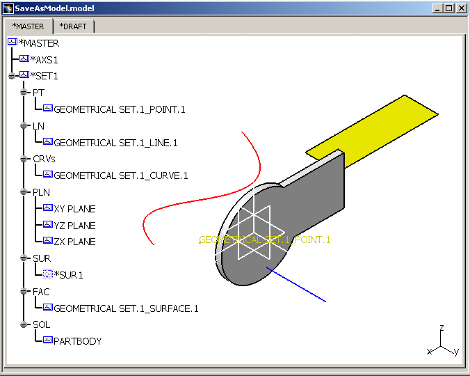
After the V5 to V4 migration, the non-volumic or non-surfacic elements are re-created (point, line, curve and face). In the Specification Tree, indicates the name of the newly created component in V5 and its container: GEOMETRICSET.1_POINT.1 for instance.
However, the volumic or surfacic components appear differently in the Specification Tree: you only have the container information of the migrated Solid because a link is kept with the CATPart.
-
In the CATPart, modify the Solid for instance. Then save the CATPart as model with the same name (SaveAsModel.model) in order to update the model.
-
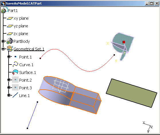
Close the Solid and re-open it. Associativity is kept between the CATPart and the model: The modifications made in V5 are reported in the model.
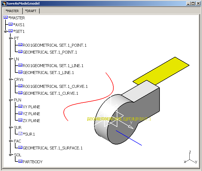
For instance, the Point identifier becomes R00....1 (R001GEOMETRIC SET.1_POINT.1) at the first synchronization of the model, this is the "old" version before the synchronization. The new one is symbolized by GEOMETRIC SET.1_POINT.1.
The Surface contains 4 Curves (or Edges) and a Face. This is why the CRVs container has 4 Curves which are the building elements for the *SUR1. But GEOMETRIC SET.1_POINT.1 in CRVs corresponds to Curve.1 (non-volumic element), a feature belonging to Geometric Set.1.
In spite of the fact that Curve.1 has not been modified, you can see that it has been recreated because the "old" version is represented by R00....1 (R001GEOMETRIC SET.1_POINT.1) and the new one by GEOMETRIC SET.1_POINT.1.
The non-associative data (R00....1 elements) is referenced in a bin layer which the user can delete if he wants.
In our example, only Solid.1 has been synchronized because it is an associative element and its geometry and specifications have been recalculated.
![]()
