Of course, you can also insert the V4 data into an existing Version 5 document alongside existing V5 drafting data by using the same procedure.
- if the thickness of V4 texts is superior to 0.2mm, V5 texts are displayed with a bold style,
- if the thickness of V4 texts is inferior or equal to 0.2mm, V5 texts are displayed with a regular style.
Additionally, the following V3 data can now be migrated directly from CATIA Version 3 to CATIA Version 5:
- V3 texts are migrated as V5 texts.
- V3 dimensions are migrated as graphical elements.
However, you can migrate V3 dimensions as V5 dimensions by using the following methodology: migrate V3 dimensions to V4 first using the V4 process, and then migrate these to V5.
-
Open a CATDrawing document.
-
In the specification tree or geometry area where the Version 4 drawing is displayed, select the view you wish to copy into CATIA Version 5. You can select several views if you prefer.
-
Put the view(s) you have selected in the clipboard. To do this, either click the Copy icon
 ,
select the Edit->Copy command or select
the Copy command
in the contextual menu.
 -
In the specification tree of the CATIA Version 5 CATDrawing document, select the appropriate sheet.
-
Now either click the Paste icon
 , select the Edit->Paste command or select the Paste
command in the contextual menu. This operation recovers the view
previously put in the clipboard.
 -
You may want to click the Fit All In icon
 to fit all data in the window.
Note that the toolbars change depending on whether a CATIA Version 4 model or a CATIA Version 5 document is selected.
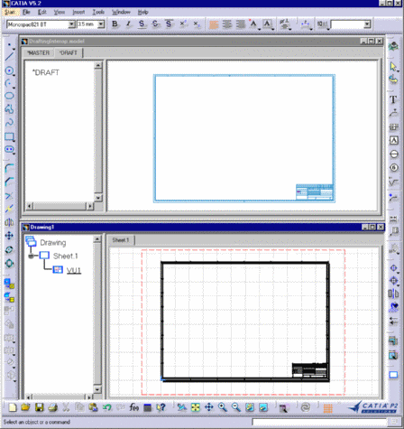
The result should look something like this (using the Window -> Tile Horizontally command):


![]()
- Whatever the standard of the V4 view was prior to being copied into CATIA Version 5, once in V5 its standard is that selected when you open the CATDrawing document.
- The smallest unit that you can copy is the view. All the elements that go to make up this view are included in the copy.
- In the V5 Drafting mode Working Views (Edit -> Working Views), the copy described above creates a V5 view with the same name as in V4. In the V5 Drafting mode Background (Edit -> Background), the V4 elements are copied into the background view of the V4 view.
- The migration of V4
drawing data to a V5 document generates a report (.rpt) file named after
the model migrated:
- on Windows:
in C:\Documents and Settings\username\Local Settings\Application Data\DassaultSystemes\CATReport - on UNIX: in /u/users/username/CATReport
This reports contains different types of information regarding the migration results:
- location and name of the input and output files,
- kind of migration performed (e.g. V4 to V5 CATDrawing),
- mode of migration performed (AS SPEC or AS RESULT)
- status of migration for each V4 element:
- Correctly/OK: migration successful
- KO: migration failed
- NOT: migration could not be performed for lack of a CATIA V5 equivalent - V4 attributes of V4 elements.
- on Windows:
- If, when importing 2D geometry, you want to create circle centers and curve end points, select Tools->Options, select the Drafting category in the left-hand column and click the V4->V5 tab. In the Geometry Import section of the window that appears, check the Create centers and end points box.
- If you want to define dimension conversion as a graphic, select the Tools->Options... command, select the Drafting category in the left-hand column and click the V4->V5 tab. In the Dimension Conversion Mode section of the window that appears, check the Convert dimension as a graphic box.
-
The V4 structure of Detail/Ditto is migrated in a V5 structure of Detail (2D component reference) /Ditto (2D component instance).
If you want to use the previous behavior (Explode Ditto) select Tools -> Options to specify the conversion mode of Dittos.
- You can copy/paste as result V4 transparent views with NHR or HLR representation (the projection mode is retrieved from the browsing).
![]()