General Principles
Remote Control
- The entire screen reacts to selections and manipulations.
- Elements and handles can be remote-activated: the mouse cursor does
not need to be over an the element or very close to interact. The element
that is closest to the mouse cursor is selected. For elements such as
faces or edges, the selection point is their barycenter.
This gives you a real productivity gain and a very fast interaction with elements and handles.
-
Using a trap as a selection means is advised. Simply press Shift and draw the trap using the left-mouse button. As a combination, you can press Ctrl to add or remove elements to the selection.
Elements are selected if their barycenter is included in the trap.
-
To manipulate and deform a curve or a surface, it is advised to double-click the curve or surface rather than clicking Modification
 in the right-hand toolbar. This helps you improve the productivity.
Escape Key
-
Use the Escape (Esc) key to exit a command.
Smart Selection
Positioning of the created geometry
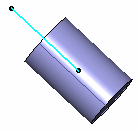
For instance, one point defines the barycenter, two points define the main axis and the middle of the points define the barycenter, three points define a plane and the normal to the plane defines the main axis, a line defines the main axis and its origin defines the barycenter, and a plane's origin defines the barycenter and the normal to the plane defines the main axis.


Some Advice
- add a geometrical set and create the styling surfaces within this geometrical set.
- create two other geometrical sets for operations and for operations' results.
- apply a pre-defined material on a subdivision surface.
- verify that the Material option is checked in the View > Render Style > Customize View command in order to visualize the mapping analysis on the surface.
- set the discretization option proportionally to the element size: in Tools > Options > General > Display > Performance, set the 3D Accuracy > Proportional option to 0.1.
- activate anti-aliasing in Tools > Options > Display > Visualization, check the anti-aliasing for Edges/Lines option.
- set the line thickness 2 to 1 (instead of 2 by default): in Tools > Options > General > Display > Thickness and Font, set the Size in pixel for Thickness 2 to 1.
Limitations
- If you wish to work using the multi-view mode, you first need to either click once in a view or perform a local modification of the view in order to activate the manipulators.
- Macro tools are not supported with the Imagine & Shape workbench.