|
|
Note that:
- The result areas are connex but given on a surface level, not on a
global one.
- The curves corresponding to the boundaries of the areas are of two
types:
- exact curves corresponding to face limits,
- approximate curves, for the other cases.
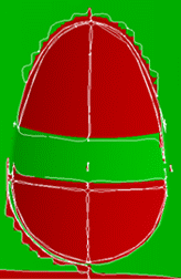
The Preview displays areas, whereas the Merge will deal with areas
made of cloud of points, limiting curves and associated surfaces. |
 |
-
Click Compare Parts
 in the Check Geometry toolbar.
-
Use the File Selection dialog box to open the
Comparison1.CATPart.
-
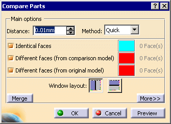
Click OK, the Compare Parts dialog box appears with the following default values.
-
Enter the Distance
used for the comparison, i.e. the distance under which two faces are
considered as identical.
The default value is 0.01 mm, the
minimum value is 0.001, the maximum value is 0.5 mm.
-
Select the Detailed
method, the comparison will be carried out on the areas.

-
The dialog box changes to:

Select the type of areas you want to visualize:
By
default all types are selected.
If you deselect a type, the corresponding
areas will be greyed.
When you click Preview, the number of
areas found
for each type is displayed in the dialog box:

The areas are visualized as follows:
The original model looks like this:

The comparison model looks like this:

In the window that displays the original model (here in white), you see
the areas that have been removed in the comparison model,
In the window that displays the comparison model (in black), you see the
areas that have been added in the comparison model (if there are some.
There is not any in the example below).

- Double-click the color patch to launch the color editor and customize
the visualization.
-
Click More to access additional parameters:
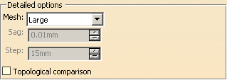
The Detailed method meshes the models to compare. You can
choose between three automatic (Large,
Medium,
Precise)
and one user-defined (User Parameters) meshing modes.
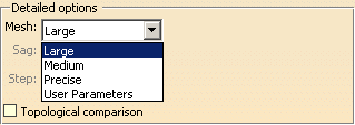
User Parameters lets you decide of the
Sag (chordal
error) and the Step (maximum length of the edges of the mesh)
values.
A small value of Step will create a mesh with many triangles,
and thus increase the quality of the comparison. But it will be
time-consuming.
Sag applies to models with curvatures. A small value of Sag in
those models will create a mesh with many triangles and thus increase the
quality of the comparison. But it will be time-consuming.
Note that the meshing starts with the Sag and Step
values you have entered, but the command may use other values to optimize
the meshing.
When you choose an automatic meshing mode, the command computes
the Sag and Step.
Topological comparison is not selected by default. Select it if
you want to search topological differences.
|
 |
- Since the models are meshed, the boundaries of areas are approximate.
- In some cases, the differences in areas cannot be found, e.g. in the
following example the difference between the original model (on the left)
and the comparison model (in the middle) is the dotted area.

It the value of Step is higher than the diameter of the hole, this hole
may not be found.
|
-
Select the layout of the comparison windows.
-
 :
vertical layout. :
vertical layout.
-
 :
horizontal layout. :
horizontal layout.
Note that the comparison model is on the black background. |
-
Click Preview:
- The comparison is made on all shown surfaces or solids.
- A progress bar appears during the comparison. The comparison can
be cancelled at any time.
- A comparison window (with two sides) appears.
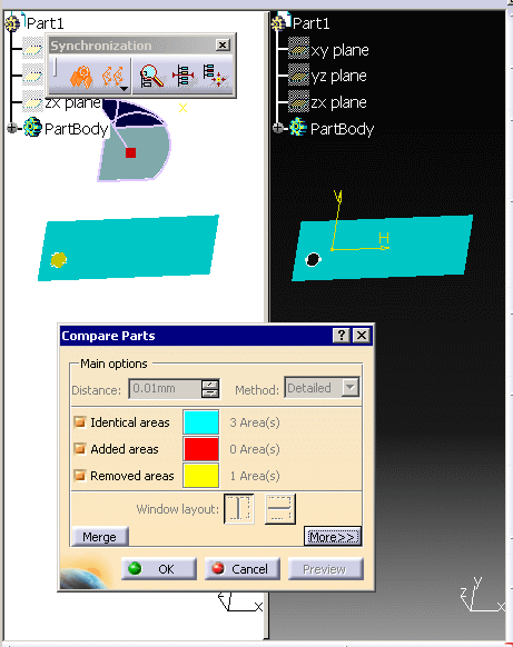
- The number of areas found for each type appears in the dialog
box.
- Those areas are highlighted in the graphic area.
- The
Synchronization toolbar appears:

|
-
Click Merge. A new dialog box appears.
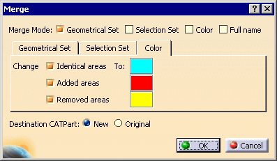
Select the required check boxes:
-
Geometrical Set to copy areas into different
Geometrical Sets, see below for more information.
-
Selection Set to place areas into different
Selection Sets
-
Color to display areas in given
Colors:
- Full name to display the
full name of areas in the specification
tree.
|
|
In the tabs described below, consider areas to be clouds of points
delimited by curves, and surfaces. When you retrieve an area, you
retrieve the clouds of points, the curves and the surfaces associated
to the areas. |
|
In the Geometrical Set tab, you can select the type of
areas you want to copy, and edit the names of the Geometrical Sets
that will contain them:

In the Selection Set tab, you can select the type of
areas you want to put in Selection Sets and edit the names of those
Selection Sets.

In the Color tab, you can select the types of faces you want to visualize and
edit the visualization color:

By default, the check boxes and colors that are
proposed by default correspond to those selected in previous steps.
|
-
Select the
Destination CATPart:
-
Original: the data will be stored in the original CATPart,
-
New: the data will be stored in a new CATPart
named MergeResult.
|
-
Click OK. Identical, added and removed areas
are extracted or computed from the compared models as Clouds of points, surfaces and
curves and are processed as follows:
- The selection of Full name check box is optional but you must select
at least one of the other three check boxes (Geometrical Set,
Selection Set or Color). You can select as many
check boxes as required (up to all).
- If you have set Destination CATPart to New, a
MergeResult_x CATPart is created to contain the result of the
comparison:
- Clouds of points, surfaces and curves from both models will be copied to MergeResult_x.
- Clouds of points, surfaces and curves are sorted in the dedicated
geometrical sets.
- If you have set Destination CATPart to Original,
the Original CATPart will contain the result of the command.
- Clouds of points and curves computed from both models will be copied to the
original CATPart.
- Surfaces from the comparison model will be copied to the
original CATPart.
- Regarding the surfaces already present in the original model, their
behavior depends on whether or not Geometrical Sets is selected or not,
see below.
- Geometrical Sets are created:
- if you have selected the Geometrical Set check box. This
option is relevant when the Destination CATPart is set to Original. This
lets you duplicate the surfaces from their original containers to the
geometrical sets dedicated to the result of the comparison. Otherwise they
would not be duplicated.
- The Identical Geometrical set contains two Geometrical sets:
- one for the clouds of points and surfaces that are
complementary to the added clouds of points, surfaces and curves,
- and one for the clouds of points and surfaces that are
complementary to the removed clouds of points, surfaces and curves.
- The Selection Sets dedicated to the comparison are created only when the
Selection Set
check box is selected, and they apply to the comparison results.
If previous Selection Sets existed in the CATParts before the comparison:
- they are lost if the Destination CATPart is set to New,
- those present in the comparison CATPart are lost if the Destination CATPart is set to
Original, whereas those of
the original CATPart still exist.
- Clouds of points, surfaces and curves are painted only when the Color check box is selected.
- As duplicate or embedded faces are ignored (considered as in NoShow), if a
counterpart face is found in the other CATPart,
it will be placed in the Different faces count, but the ignored
faces
will not be copied to a Geometrical Set,
or placed in a Selection Set, or displayed in a given color.
In extreme cases, the Geometrical Set containing only ignored faces will not be
created.
|
|