Creating Inflection Lines

This task shows how to create inflection lines on a surface for analysis purposes.
Inflection lines are curves which curvature value necessarily is 0.
The system detects, within the planes parallel to the one defined by the compass, all points of the surface at which the curvature value is null, meaning that in these points, the curvature orientation is changing, and links them together into curves.
Open the InflectionLine1.CATPart document. 
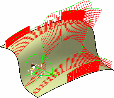
It contains a surface on which a cutting plane Analysis has been performed.
  1. Drag and drop the compass onto the zx plane.


  1. Select the surface to be analyzed.

 
  1. Click the Inflection Line icon:

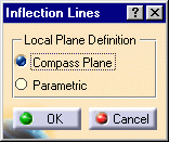
The Inflection lines dialog box appears.


The Inflection lines dialog box allows you to define the local plane:

  • the compass base plane (Compass Plane)

  • the surface parametric directions (Parametric)

 
  1. Define the plane used to compute the inflection lines on the surface.

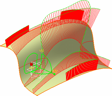
Once the local plane is defined, inflection lines are automatically displayed on the surface.

 
  1. Hide the Cutting Plane analysis, using the Hide/Show icon to see the inflection lines better.

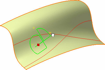
  1. Grab the compass by its tip (w) and drag it along.

The compass base plane's orientation being modified, the inflection lines are updated accordingly:

 
  1. Click OK in the Inflection Line dialog box to create the analysis as an element in the specification tree.

  • Creating and retaining inflection lines on a surface is especially useful to determine at which points the curvature of the intersection between the cutting planes and the surface is null.

  • Used in conjunction with the Inflection area option of the Surfacic Curvature Analysis command, you can notice that these lines always are created within the green.

  • When you select the geometrical set as an input in the specification tree, all the elements included in this geometrical set are automatically selected too.