This task shows how to impose nodes (as mesh specifications) around a selected hole.
Open the Sample03.CATAnalysis document from the samples directory.
-
Enter the Surface Mesher workshop.
For more details, refer to Entering the Surface Mesher Workshop.
-
Click Elements Distribution around Hole
 in the Local Specifications toolbar.
The Mesh around Holes dialog box appears.
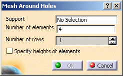
- Support: lets you select the hole on which you want to impose nodes.
- Number of elements: lets you enter the number of elements you want to create around the selected hole.
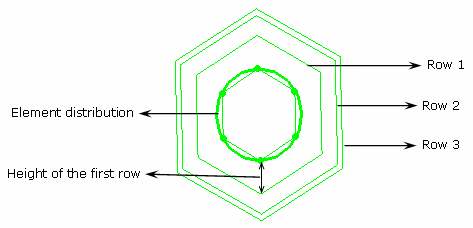
- Number of rows: lets you select the number of rows around the hole (one, two or three rows).
- Specify heights of elements: lets you specify the
height of the three first row around the hole.
If this option is deactivated, the mesh around the selected hole will be automatically done by the algorithm.

- Heights of row 1: lets you specify the height of the first row.
- Heights of row 2: lets you specify the height of the second row.
- Heights of row 3: lets you specify the height of the third row.
-
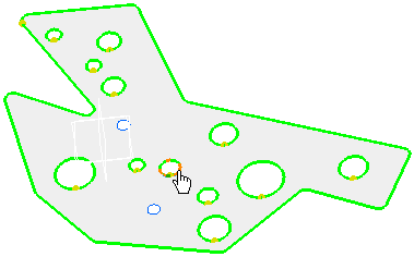
Select a hole as Support.
Note that whatever the number of curves making out the holes, multi-selection is automatic. You do not need to select each curve making out the hole.
-
Enter the desired Number of elements value in the Mesh Around Holes dialog box.
In this particular example, enter 6 as Number of elements value.
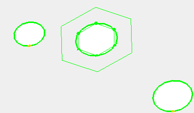
-
Select the Number of rows.
In this particular example, set the Number of rows value to 3.
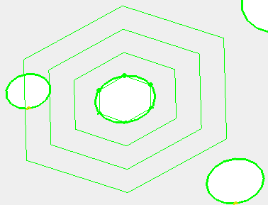
-
Activate the Specify heights of elements option.
-
Specify the height for each row.
In this particular example, enter:
- 4mm as Heights of row 1 value,
- 2mm as Heights of row 2 value,
- 1mm as Heights of row 3 value.
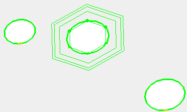
-
Click OK.
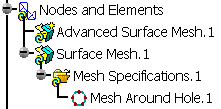
A Mesh around Hole.1 object belonging to Mesh Specifications.1 appears in the specification tree under the Surface Mesh.1 mesh part.
