This task shows how to impose nodes (as mesh specifications) either on free edges or on constrained edges.
-
Open the Sample06.CATAnalysis document from the samples directory.
-
Enter the Surface Mesher workshop.
For more details, refer to Entering the Surface Mesher Workshop.
-
Click the Element Distribution icon
 from the Local Specifications toolbar.
The Edit Elements Distribution dialog box appears.
- Support: lets you select the edge on each you want to impose nodes.
- Type:
- Uniform: the distance between all the distributed
nodes will be the same.
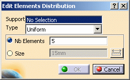
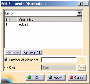
- Number of elements: lets you define the element distribution by imposing a number of division on the selected edge.
- Size: lets you define the element distribution by imposing a mesh size on the selected edge.
- Arithmetic: the distance between the distributed
nodes will be defined by a common difference computed with the
following parameters.
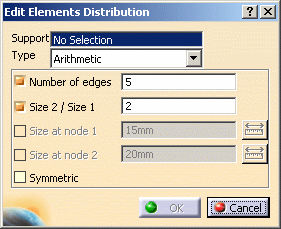
- Number of Edges: lets you specify how many edges you want.
- Size 2 / Size 1: lets you specify the ratio between the lengths of the last and the first distribution edge.
- Size at node 1: lets you specify the length of the first edge of the distribution.
- Size at node 2: lets you specify the length of
the last edge of the distribution.

Note that you have to specify two and only two parameters among the four.
- Symmetric: lets you specify if the distribution should be symmetric or not.
- Geometric: the distance between the distributed
nodes will be defined by a common ratio computed with the
following parameters.
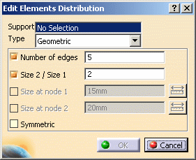
- Number of Edges: lets you specify how many edges you want.
- Size 2 / Size 1: lets you specify the ratio between the lengths of the last and the first distribution edge.
- Size at node 1: lets you specify the distance between the two first nodes of the distribution.
- Size at node 2: lets you specify the distance
between the two last nodes of the distribution.

Note that you have to specify two and only two parameters among the four.
- Symmetric: lets you specify if the distribution should be symmetric or not.
- User Law: the distance between the distributed
nodes will be defined by a knowledge law previously defined in
the Product Advisor workbench.
For more details about the user law, refer to the Infrastructure User's Guide - Advanced Tasks - Using Knowledgeware Capabilities.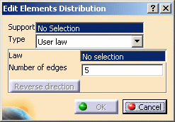

A user law must have been defined.
- Law: lets you select the desired law.
- Number of edges: lets specify how many edges you want.
- Reverse direction: this button lets you reverse the direction of distribution.
- Uniform: the distance between all the distributed
nodes will be the same.
-
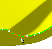
Select the edge on which you want to distribute nodes.
You can select several edges on the condition they are continuous to each others.
-
Set the desired parameters in the Edit Elements Distribution dialog box.
-
If needed, modify the number of the nodes or size. In this case, enter 3 as new value (Number of elements).
-
Click OK in the Edit Elements Distribution dialog box.
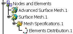
A Mesh Specifications.1 set containing the Elements Distribution.1 specification appears in the specification tree under the Surface Mesh.1 mesh part.
