This task shows you how to add or remove constraints for a selection of vertices.
-
Open the Sample06.CATAnalysis document from the samples directory.
-
Enter the Surface Mesher workshop.
For more details, refer to Entering the Surface Mesher Workshop.
For a better visualization of constrained vertices, you can
change the color of the part.
To do this:
- Right-click Surface.1 (under Links Manager.1 -> Part1 -> Geometrical Set.1) in the specification tree.
- Select the Properties contextual menu.
- Select the desired Fill Color in the Graphic tab.
- Click OK in the Properties dialog box.
-
Click Add/Remove Constraints on Vertex
 in the Local Specifications toolbar.
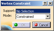
The Vertex Constraint dialog box appears:

- Support: lets you select the vertices on which you
want to add or remove constraints.

Multi-selection of vertices is available.
- Mode: lets you specify if you want to add or remove
constraints on the selected vertices.
- Constrained: lets you add constraints on the selected vertices.
- Unconstrained: lets you remove constraints on the selected vertices.
- Support: lets you select the vertices on which you
want to add or remove constraints.
-
Select one or several constrained vertices as Support.
In this particular example, select a yellow-highlighted vertex as shown below:

-
Select Unconstrained as Mode option in the Vertex Constraint dialog box.
-
Click OK.
The unconstrained vertex is not yellow-highlighted anymore.
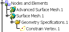
A Constrain Vertex.1 object belonging to Geometry Specifications.1 appears in the specification tree under the Surface Mesh.1 mesh part.

-
Click Add/Remove Constraints on Vertex
 in the Local Specifications toolbar.
The Vertex Constraint dialog box appears.
Note that the vertex you selected in the second step is now blue-highlighted:

-
Select one or several unconstrained vertices as Support.
In this particular example, select a blue-highlighted vertex as shown below:

-
Select Constrained as Mode option in the Vertex Constraint dialog box.
-
Click OK.
The vertex is now yellow-highlighted:

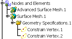
A Constrain Vertex.2 object belonging to Geometry Specifications.1 appears in the specification tree under the Surface Mesh.1 mesh part.

![]()