This task shows you how to specify holes in the geometry you want to be ignored by the meshing process.
-
Open the Sample03.CATAnalysis document from the samples directory.
-
Enter the Surface Mesher workshop.
For more details, refer to Entering the Surface Mesher Workshop.
-
Click Boundary Simplifications
 in the Local Specifications toolbar.
The Hole Suppression dialog box appears:
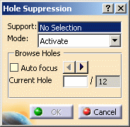
- Support: lets you select the holes you want to
ignore or to be taken into account in the meshing process.

Multi-selection of holes is available.
- Mode: lets you specify if you want to ignore or to
take into account the selected holes.
- Activate: lets you take into account the selected holes.
- Inactivate: lets you ignore the selected holes.
- Browse Holes:
- Auto Focus: lets you zoom in activated holes.
- Current Hole: gives you the number of detected holes (holes that are in active mode) and lets you visualize a particular hole either by entering a number or by clicking buttons.
- Diameter: gives you information about the diameter of the hole you focus on.
- Auto Focus: lets you zoom in activated holes.
- Support: lets you select the holes you want to
ignore or to be taken into account in the meshing process.
-
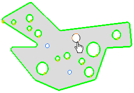
Select a green-highlighted hole as shown below:
-
Select Inactivate as Mode option in the Hole Suppression dialog box.
-
Click OK.
The hole is blue-highlighted and will then be ignored by the mesher.
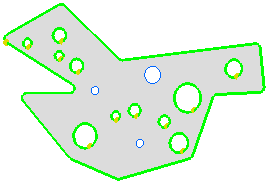
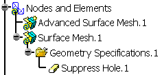
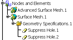
A Suppress Hole.1 object belonging to Geometry Specifications.1 appears in the specification tree under the Surface Mesh.1 mesh part.
-
Click Boundary Simplifications
 in the Local Specifications toolbar.
The Hole Suppression dialog box appears.
-
Select a blue-highlighted hole as shown below:
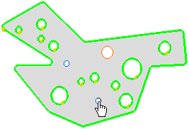
Note that: in this example, you have to select the both side of the hole.
The Hole Suppression dialog box is updated: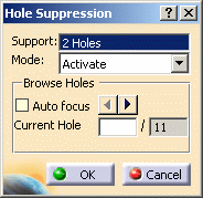
-
Select Activate as Mode option in the Hole Suppression dialog box.
-
Click OK.
The hole is green-highlighted and will be taken into account by the mesher.
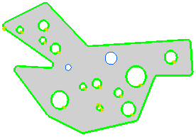
A Suppress Hole.2 object belonging to Geometry Specifications.1 appears in the specification tree under the Surface Mesh.1 mesh part.
-
Click Mesh The Part
 .
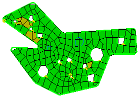
.The meshed part now appears with ignored and non-ignored holes.
-
Click OK in the Mesh The Part dialog box.
![]()