This task shows how to display subsets of free edges and thereby quickly visualize incompatible mesh. A subset of free edges is a connected component of free edges.
If an edge of 2D mesh is shared with a 3D mesh (using capture, coating and extrusion functionalities) this edge will not be free anymore.
Open the Sample05.CATAnalysis document from the samples directory.
The mesh elements are assigned green, yellow or red colors.
For more information, refer to Colors
Meaning in the Before You Begin chapter.
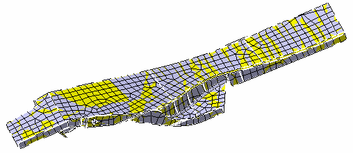
In this particular example, both the geometry and the mesh are displayed:
-
Click Free Edges
 in the Mesh Analysis Tools toolbar.
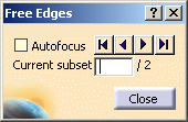
The Free Edges dialog box appears.
-
Autofocus: lets you focus on a particular free edges subset.
-
The browse buttons allow you to scan the free edges subsets.
-
Current subset: gives you the number of subsets of free edges and lets you visualize a particular subset either by entering a number or by clicking the browse buttons.
In this particular example, two subsets of free edges are detected.
-
The geometry is automatically hidden as soon as the Free Edges command is selected. Only mesh elements and free edges are displayed:
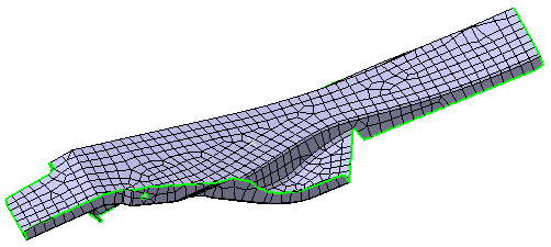
The free edges are automatically drawn in green and allow quickly checking mesh validity:
Free Edges not selected
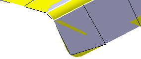
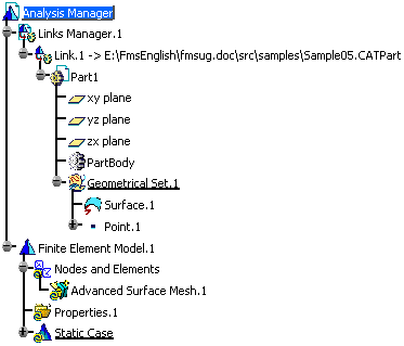
Free Edges selected
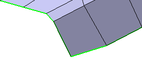
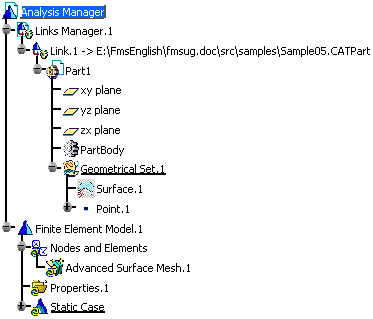
-
-
Select the Autofocus check box.
The first subset is automatically focused on.
-
Click the
 button
to focus on the second subset.
 -
Click Close.
The geometry is automatically displayed.
To do this, select View > Render Style > Wireframe (NHR).