You can find here the recommended methodology to mesh spot welds using the compatible mode.
The recommended methodology is different according to the weld modeling option you will choose in the Spot Welding Connection Mesh dialog box:
To create an analysis connection, you have to install the Generative Assembly Structural Analysis (GAS) product.
1D Weld Modeling
This scenario is recommended with the following weld modeling options:
- Beam
- Rigid
- Rigid-Spring-Rigid
- Spring-Rigid-Spring.
Open the sample26.CATProduct document from the sample directory.
-
Select Start > Analysis and Simulation > Advanced Meshing Tools.
The New Analysis Case dialog box appears.
Click OK. -
Create a point analysis connection.
-
Click Point Analysis Connection
 in the Analysis Support toolbar.
 -
Select:
- Fill.1/Part1 as First Component
- Fill.1/Part2 as Second Component
- Point.4/Part3 as Points.
-
Click OK in the Point Analysis Connection dialog box.

For more details about analysis connections, refer to Analysis Connections chapter in the Generative Structural Analysis User's Guide. -
-
Right-click the Analysis Connection.1 object in the specification tree and select Update all analysis connections.
-
Mesh the first support.
To do this:-
Click Advanced Surface Mesher
 .
. -
Select the Part1 -> Fill.1 feature in the specification tree.
-
Set the global parameters.
-
Click OK in the Global Parameters dialog box.
-
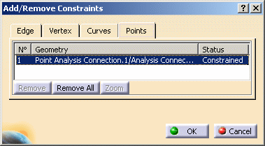
Click Add/Remove Constraints
 in the Local Specifications toolbar and select the
Points tab.
 -
Select the Point Analysis Connection.1 object in the specification tree.

-
Click OK in the Add/Remove Constraints dialog box.
-
Click Exit
 to exit the Advanced Surface Mesher workshop.
-
-
Mesh the second support (Part2 -> Fill.1) in the same way as the first support.
-
Click Spot Welding Connection Mesh
 in the Welding Meshing Methods toolbar.
 -
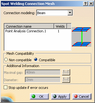
Set the following parameters in the Spot Welding Connection Mesh dialog box:
- Beam as Connection modeling option
- Point Analysis Connection.1 as support
- Compatible as Mesh Compatibility option.

-
Click Apply and then OK in the Spot Welding Connection Mesh dialog box.
![]()
Hexahedron Weld Modeling
This scenario is recommended only with the Hexahedron weld modeling option.
Open the sample26.CATProduct document from the sample directory.
-
Select the Start > Analysis and Simulation > Advanced Meshing Tools menu.
The New Analysis Case dialog box appears.
Click OK. -
Create a line analysis connection.
-
Click the Point Analysis Connection icon.
-
Select:
- Fill.1/Part1 as First Component
- Fill.1/Part2 as Second Component
- Point.4/Part3 as Points.
-
Click OK in the Point Analysis Connection dialog box.

For more details about analysis connections, refer to Analysis Connections chapter in the Generative Structural Analysis User's Guide. -
-
Right-click the Analysis Connection.1 object in the specification tree and select Update all analysis connections.
-
Mesh the first support.
To do this:-
Click Advanced Surface Mesher
 .
. -
Select the Part2.2 -> Fill.1 feature in the specification tree.
-
Select the Quadrangle mesh type and set the desired global parameters.
-
Click OK in the Global Parameters dialog box.
-
Click Exit
 to exit the Advanced Surface Mesher workshop.
-
-
Mesh the second support (Part2.1 -> Fill.1) in the same way as the first support.
-
Click Spot Welding Connection Mesh
 in the Welding Meshing Methods toolbar.
 -
Set the following parameters in the Spot Welding Connection Mesh dialog box:
- Hexahedron as Connection modeling option
- Point Analysis Connection.1 as support
- Compatible as Mesh Compatibility option.
-
Click Apply and then OK in the Spot Welding Connection Mesh dialog box.