-
Click the Protected Feature icon
 .
.
The Protected Feature dialog box that appears displays the Prism icon as the default shape to be created. Keep this option.
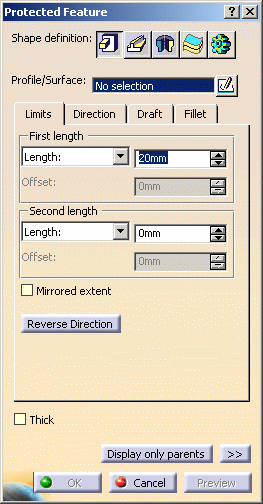
First Protected Prism
-
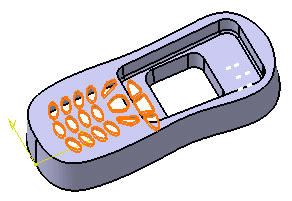
Select Key holes as the profile to be used.
-
Enter 20mm in the First length field.
-
Click the Direction tab to ensure that the direction of the features will be normal to the profile plane.
-
As you do not need to draft the feature nor fillet its edges, simply click OK to create the protected prism.
Second Protected Prism
-
To create the second protected prism, click the Protected Feature icon
again. -
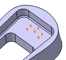
Select HP Holes as the profile to be used.
-
Enter 20mm in the First length field.
-
Click the Direction tab to ensure that the direction of the features will be normal to the profile plane.
-
As you do not need to draft the feature nor fillets its edges, simply click OK to create the protected prism.
Third Protected Prism
Now you will create a third protected prism that corresponds to the area reserved for the phone electronic mechanism.
-
Select Reserved Space as the profile to be used.
-
Enter 4mm in the First length field.
-
Enter 2mm in the Second length field.
-
Click the Draft tab.
-
To define the draft angle, set the Draft behavior option to Intrinsic to feature. Options are now displayed.
-
Set the Angle option to 3deg.
-
Set the first limit as the neutral element
-
Click OK to confirm.
The specification tree indicates these operations under the names of Protected Prism.2, Protected Prism.3 and Protected Prism.4.
In a Nutshell
Creating a protected volume:
|
To know more about this capability, refer to Protected Feature.