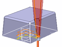
A PowerCopy is a set of features (geometric elements, formulas, constraints and so forth) that are grouped in order to be used in a different context, and presenting the ability to be completely redefined when pasted.
This PowerCopy captures the design intent and know-how of the designer thus enabling greater reusability and efficiency.
-
Prior to defining the power copy element, use the Tools -> Options -> Infrastructure -> Part Infrastructure and select Display tab to check if parameters and formulas are defined for the part: check the Parameters and Relations options in Display In Specification Tree if they are not checked.
Taking a look at the specification tree, the PowerCopyInitial.CATPart document contains three parameters and eight formulas.
-
To create the power copy, select Insert ->Knowledge Templates -> Power Copy... .
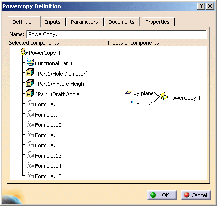
The Powercopy Definition dialog box is displayed. -
From the specification tree, select the elements to be included in the PowerCopy.

we strongly recommend you locate all required functional and GSD features within functional sets prior to generating powercopies. In our example, select the three parameters, all the formulas and Functional Set.1 to select the cutouts of our geometry.


The PowerCopy Definition dialog box is automatically filled with information about the selected elements.

-
Define the PowerCopy as you wish to create it: for details about all options, see Powercopy Definition Dialog Box. Click the Parameters tab.
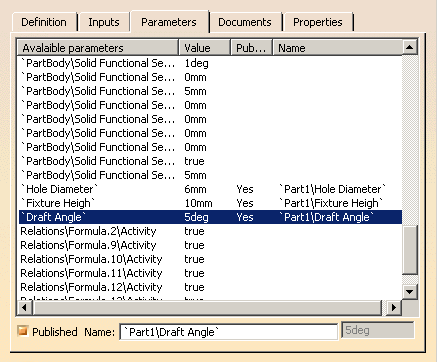
This tab allows you to define which of the parameter values used in the PowerCopy you will be able to modify at instantiation time. -
Double-click the three parameters to make them public.
The Published Name option is then checked for each of them, indicating that the parameters can be modified at instantiation time.

-
Click OK to create the PowerCopy.
The PowerCopy.1 node is displayed in the specification tree, just below the Relations node.