- explains both the behavior and parameters existing in Path Finder
- gives some methodologies and ideas to use Path Finder
- to find a first path,
- to refine a roughly defined path (manually)
- to define a path automatically (when time to display the assembly is too long for manual path definition)
- to perform automatically checks in batch mode.
Basic Path Finder Options

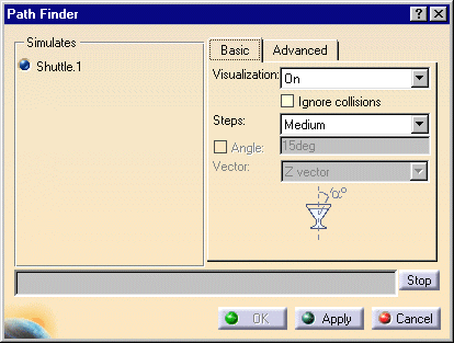
Visualization
- On: Each displacement of the part to be moved is displayed
- Off: No displacement of the part to be moved is displayed
- Strombo: Only one displacement is displayed for
twenty computed displacements.

Performances are better with the Off option set than with Strombo option set and better with Strombo than with On option set. Strombo mode can be more user-friendly than Off mode as some displacements are displayed. 
If you work with the Off option set, you will not be able to to stop the computation using the Stop button.
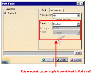
Steps
High, Medium and Low are the options available in the list. In addition, you can select Advanced.
Angle
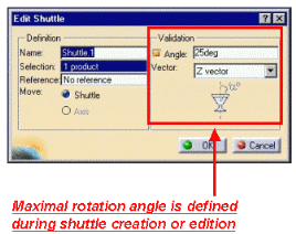
If a maximal rotation angle has been defined while creating the shuttle, this option is available. If the Angle check box is selected, the maximal angle will be considered and taken into account in the path finder computation.


Advanced Path Finder Options
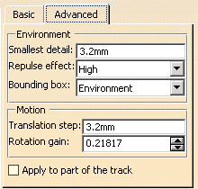
- Environment
- Motion
- Apply to part of the track
First, V5 browses the environment considering parts in session. This
builds an internal 3D map describing the obstructions and possible paths.
Settings for this first process are set in the frame called
Environment.
Then, this internal 3D map is used by the Path Finder algorithm
as a global indication to find a way out. Several motions or displacements
are successively tried along the path and clashes are computed for each
trial. Settings for this second process are set in frame called
Motion.

Environment
Smallest detail is the size which will be considered to create a 3D map.
For example, if the Smallest detail value equals
7mm:
- if a hole has a size of 6.9 mm, it will not be seen as a hole in the internal 3D map
- if a boss has a size of 1 mm, it will be seen as a boss of 7 mm in
the internal 3D map
Smallest detail value is not the accuracy considered for clash computation.
For clash computation, this is the sag value, which is taken into account. The clash computation accuracy is two times lower than the sag value.
|
|
As the accuracy of the map is not linked to the clash accuracy, it
could be more convenient for the algorithm to comprise a rough map
within which it could navigate, than one containing too many details
and possibilities.
For a first usage of Path Finder, using a big value for Smallest detail can be useful to blind useless holes. |
- Repulse effect, The higher the repulse effect is set, the more the rotation motion is eased and the smoother the path. With a lower repulse effect, rotating the part becomes more difficult as more clashes occur
- Resizing the Bounding box changes the area in
which Path Finder
 attempts to make a move.
Altering the bounding box option can significantly reduce computation time necessary to create the 3D map. But resizing too much may create holes in the internal 3D map, which leads to unsuccessfully tried displacements afterwards.
Motion
Translation step is the distance the part will be moved, therefore, the distance between successively analyzed locations will be equal to the translation step.
Clash analysis is performed for each location but not between these locations. Indeed, it is a discrete analysis but not a continuous one
Only locations where no clash occurs are kept in the simulation provided by Path Finder
Rotation gain allows you to define how
much a part will be rotated between two analyzed locations
- If rotation gain equals 1, displacement at the extremity of the part will be equal to the step value
- If rotation gain equals 2, displacement at the extremity of the part will be equal to twice the step value
- If rotation gain equals 0.1, displacement at the extremity of the part will be ten times smaller than the step value.
Apply to part of the track
Selecting this check box means that you are prompted to select a
beginning and end segment of the track that defines the area of the track
to which you want to apply Path Finder
![]() .
.
Leaving the check box unselected (the default) means that Path
Finder
![]() will apply to the entire path.
will apply to the entire path.
Input for Path Finder
Using such more complete input will make algorithm converge quicker.
Input for a new usage of Path Finder can be a resulting of a previous usage of path finder, even if this previous usage did not provide a complete simulation without clashes.
It is possible to loop on several Path Finders, starting with a rough translation step value and refining this value in the next usage.