- The dimension anchor point can be positioned on the center/axis or the edge of the selected geometry of revolution.
- This behavior cannot be available once the dimension is created.
- The default positioning is defined in the Dimension options.
- Improve the highlight of the related geometry, see Highlighting of the Related Geometry for 3D Annotation.
- Make sure that the Center or Axis option is selected, see Dimension options.
-
Select the first hole as shown on the part.
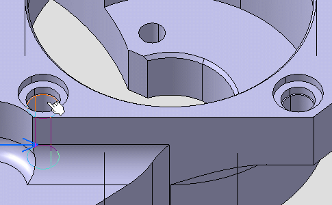
-
Select the second hole as shown on the part. A diameter dimension appears on the first hole during the creation process.
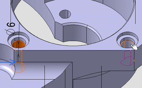
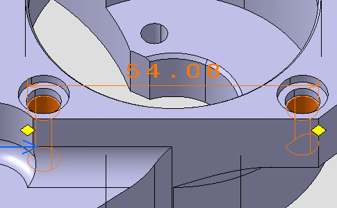
The dimension is pre-created between the two holes and its dimension anchor points are positioned on their edges. Make sure that the Edge option is selected, see Dimensions options.
Two yellow diamond manipulators represent the dimension anchor points.
-
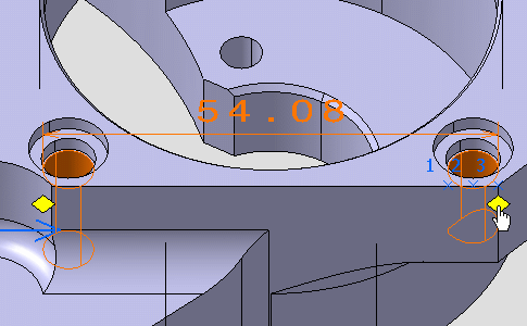
Move the mouse cursor on the yellow diamond as shown to reveal all the available dimension anchor point locations.
These locations are numbered and represented by blue crosses.
-
Drag the yellow diamond as shown on the location number 2 that is representing the hole axis.
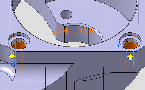
-
Drag the second yellow diamond on the location number 2 that is representing the hole axis. The dimension is modified accordingly.
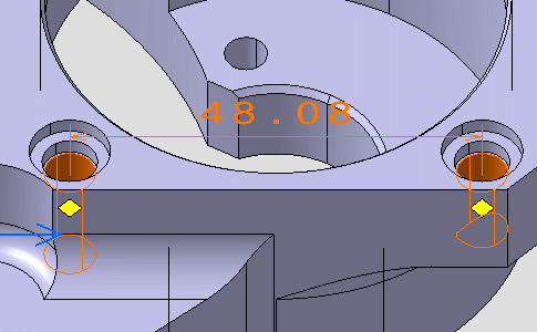
-
Click outside the geometry to create the dimension.