This task shows you how to create a Line Analysis Connection Within
One Part.
Line analysis connections within one part are used for simulating welding
seam onto parallel faces, belonging to the same part.
Only available with the Generative Assembly Structural Analysis (GAS) product.
Open the sample09.CATAnalysis from the sample directory.
-
Click Line Analysis Connection within one Part
 in the Analysis Supports toolbar.
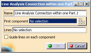
The Line Analysis Connection within one Part dialog box appears.

- Name: lets you change the name of the connection.
- First component: lets you select the part that will
support the connection.

You can select one body (2D or 3D) or one mesh part.
- Select Mesh Parts: this button is available only
if a support is selected.
For more details, refer to Selecting Mesh Parts.
- Select Mesh Parts: this button is available only
if a support is selected.
- Lines: lets you select the welding line.

Multi-selection is not available.
- Guide line on each component: lets you select a
second line to guide the connection orientation.

The projection of the welding line on guide line is possible if:
- The guide line is face to face with the welding line.
- The length of the guide line is equivalent to the length of the welding line.
- The welding line and the guide line features are equivalent (that means that if the welding line is a curve feature, the guide line must be a curve feature).
-
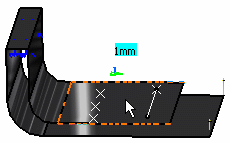
Select the open body.
In this particular example, select Extrude.1.

-
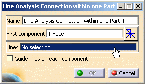
Activate the Lines field.
To do this, select the Lines edit box as shown below:

-
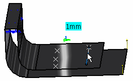
Select the line.
In this particular example, select Open body.2 (Points) - Line.1.

-
Click OK in the Line Analysis Connection within one Part dialog box.
The Line Analysis Connection within one Part.1 connection appears in the specification tree under the Analysis Connection Manager.1 set.

- You can update analysis connections.
For more details, refer to Updating Analysis Connections. - You can now apply a connection property on the connection you just
have created.
For more details, refer to Creating Seam Welding Connection Property.