This task shows you how to create a General Analysis Connection.
General analysis connections are used for connecting any
part from an assembly with or without handler point, on an assembly model.
This can be performed between any type of geometry.
This is very useful when you want to benefit from the representation of
part without actually designing this part.
You can also connect two sub-analyses in an Analysis Assembly
context using the general analysis connection.
For more details about the analysis assembly context, refer to
Analysis Assembly.
- Only available with the Generative Assembly Structural Analysis
(GAS) product
 .
. - The connection has to connect two components.
A component can be:- a vertex,
- an edge or a multi-selection of edges belonging to the same feature,
- a surface or a multi-selection of surfaces belonging to the same part body,
- a mechanical feature (i.e. sketch, pad, assemble, remove, ...),
- a group (defined using the Groups toolbar in the
Generative Structural Analysis workbench or using the
Create Group contextual menu in the Generative Structural
Analysis workbench or in the Advanced Meshing Tools
workbench).
- You can select groups (defined using the Groups toolbar) as component only if they have been defined in the sub-analyses.
- You can select groups under mesh part (defined using the Create Group contextual menu) as component.
- A connection with a vertex on one side does not accept a handler point.
Open the sample42.CATAnalysis from the samples directory.
-
Click General Analysis Connection
 in the Analysis Supports toolbar.
The General Analysis Connection dialog box appears.
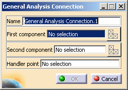
- Name: lets you change the name of the connection.
- First component: lets you select the first "side" of
the part that will support the connection.

- Multi-selection is not available for vertex and mechanical feature.
- Multi-selection of edges or surfaces must be homogeneous and must belong to the same mesh part.
- Multi-selection of groups is not available.
- Select Mesh Parts: this button is available only
if a support is selected.
For more details, refer to Selecting Mesh Parts.
- Second Component: lets you select the second "side"
of the part that will support the connection.

- Multi-selection is not available for vertex and mechanical feature.
- Multi-selection of edges or surfaces must be homogeneous and must belong to the same mesh part.
- Multi-selection of groups is not available.
- Select Mesh Parts: this button is available only
if a support is selected.
For more details, refer to Selecting Mesh Parts.
- Handler point: lets you specify an optional handler
point.

A connection with a vertex on one side does not accept a handler point.
-
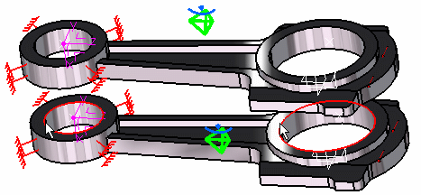
Select the first component.
In this particular case, select two edges belonging to the Part3 (Part 3.1).
-
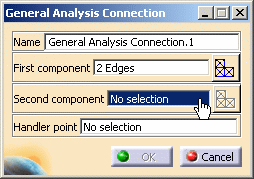
Activate the Second component field.
To do this, select the Second component edit box as shown below:
-
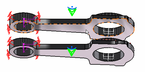
Select the second component.
In this particular case, select a surface belonging to the Part3 (Part 3.2).
-
Optionally, you can activate the Handler point field by selecting the Handler point edit box.
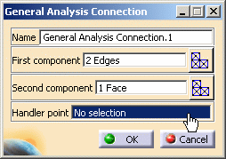
In this particular example, you do not need to select a handler point.
-
Optionally, select a point as handler point.
-
Click OK.
A symbol representing the general connection is visualized.
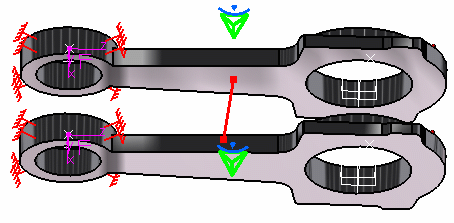
The General Analysis Connection.1 connection appears in the specification tree under the Analysis Connection Manager.1 set.

- You can update analysis connections.
For more details, refer to Updating Analysis Connections. - You can now apply a connection property on the connection you just
have created.
For more details, refer to the Connection Properties section.