This task shows you how to import a composite property.
In the analysis context, composite properties will be
applied on 2D geometries on which composite design has been defined in the
Composite Design workbench.
For more details, refer to the Composite Design User's Guide.
You will see here how to generate a composite finite element model from the design by:
Only available with the ELFINI Structural Analysis (EST) product.
Definition Based on Zones
Open the sample06.CATAnalysis document.
-
Click Imported Composite Property
 in the Model Manager toolbar.
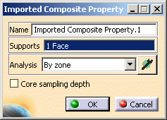
The Imported Composite Property dialog box appears.
- Name: lets you modify the name of the property.
- Supports: lets you select a 2D body as support.
- Analysis: lets you choose the zone approach or the
ply approach.
- By zone: lets you choose the zone approach.

- Zones must have been defined in the Composite Design workbench.
- Transition zones defined in the Composite Design workbench are ignored.
- By ply: lets you choose the ply approach.
- Component Edition button
 : lets you filter by zones
or by plies.
When clicking this button, the Filter Definition dialog box appears to lets you select the zones or plies.
- By zone:

-
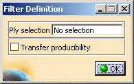

- By zone:
- By zone: lets you choose the zone approach.
- Core sampling depth: lets you define an optional
tolerance to control the number of plies or zones taken into
account in the analysis context.

-
Select the support as shown below.
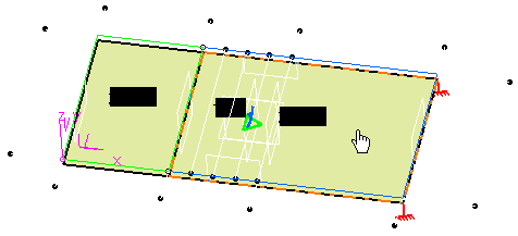
The Imported Composite Property dialog box is updated as shown below:
-
In the Analysis list, select By zone.
-
Click OK in the Imported Composite Property dialog box.
An Imported Composite Prorperty.1 property appears in the specification tree under the Properties.1 set.
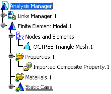
Note that the applied materials are not visible under the Materials.1 set in the specification tree.
However you can edit and change the material properties.
To do this:-
Select the File > Desk menu.
-
Right-click the CompositesCatalog.CATMaterial document and select the Open contextual menu.
-
Double-click a material to edit it.
The Properties dialog box appears.
-
Change the desired parameters in the Analysis tab of the Properties dialog box.
For more details about this tab, refer to Modifying Material Physical Properties in this guide.

The only allowed materials in the composite property definition are Isotropic, Orthotropic 2D and Fiber.
-
Click OK in the Properties dialog box.
In this particular example, do not change material physical properties.
-
-
Click Compute
 ,
select Mesh Only in the Compute dialog box and click OK.
 -
Right-click the Properties.1 set and select the Generate Image contextual menu.
-
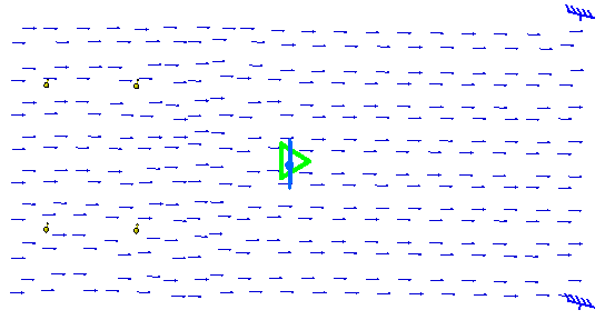
Select Composite angle symbol as image and click OK in the Image Generation dialog box.
The following image visualization is displayed:
-
Edit the image you just generated.
In this particular example:
-
Double-click the Composite angle symbol.1 image.
-
Click the More button to expand the Image Edition dialog box.
-
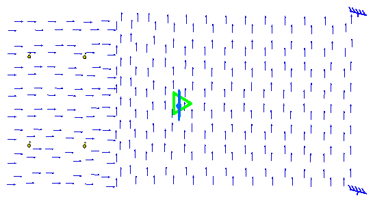
Enter 6 as Lamina value.
-
Click OK in the Image Edition dialog box.
The image visualization is updated and lets you visualize the sixth lamina:
-
Definition Based on Plies
Open the sample06.CATAnalysis document.
-
Click Imported Composite Property
 in the Model Manager toolbar.
The Imported Composite Property dialog box appears.
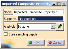
To know more about the Imported Composite Property dialog box, refer to the dialog box description.
-
Select the support as shown below.

The Imported Composite Property dialog box is updated as shown below:
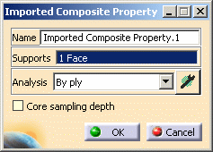
-
In the Analysis list, select By ply.
-
Click OK in the Imported Composite Property dialog box.
An Imported Composite Prorperty.1 property appears in the specification tree under the Properties.1 set.

In this particular example, do not change material physical properties.
-
Click Compute
 ,
select Mesh Only in the Compute dialog box and click OK.
Definition Based on Plies with Producibility
Open the sample64.CATAnalysis document.
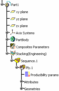
-

The Imported Composite Property dialog box appears.
To know more about the Imported Composite Property dialog box, refer to the dialog box description. -
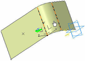
-
An Imported Composite Prorperty.1 property appears in the specification tree under the Properties.1 set.

-
Click Compute
 ,
select Mesh Only in the Compute dialog box and click OK.
 -
The Imported Composite Property dialog box appears.
-

-
Click Compute
 ,
select Mesh Only in the Compute dialog box and click OK.
 -
Generate a Composite angle symbol image on the Properties.1 set.
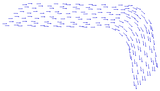
![]()