This task shows how to create a Bolt Tightening Connection between two parts.
-
Only available with the Generative Assembly Structural Analysis (GAS) product
 .
. -
To have precisions and to know restrictions, refer to About Connection Properties.
-
The Gradient method is not available if several Bolt Tightening connections reference the same degree of freedom. In this case, try to choose another method type.
As a support, the bolt tightening connection requires a surface constraint of face-face type between the bolt thread and the bolt support tapping. Note that both these surfaces should be coincident.
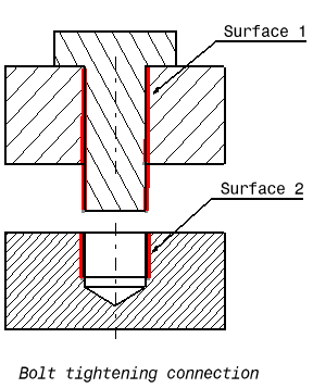
In this example, Surface 1 and Surface 2 are supports for the assembly constraint of surface contact type.
A bolt tightening connection is a connection that takes into account pre-tension in bolt-tightened assemblies. The computation is carried out according to the two-step traditional approach. In the first step of the computation, the model is submitted to tension forces relative to bolt tightening by applying opposite forces on the bolt thread and on the support tapping, respectively. Then, in the second step, the relative displacement of these two surfaces (obtained in the first step) is imposed while the model is submitted to user loads. During these two steps, the bolt and the support displacements are linked in the direction normal to the bolt axis. Since bodies can be meshed independently, the Bolt Tightening Connection is designed to handle incompatible meshes.
The Contact Connection relations take into account the elastic deformability of the interfaces.
The program proceeds as follows:
- each node of the finer surface mesh is projected parallel to the local outer normal of the first surface onto the second surface mesh.
- a projection point is located whenever possible at the intercept of the projection direction with the second surface mesh (extrapolated at the face boundary by roughly half an element width).
- if a projection point exists, the start node is connected by a node-to-face element with Bolt Tightening property to all nodes of the element face on which the projection point has landed.
- a set of join-type relations (involving interpolation using element shape functions) is computed between the degrees of freedom of the start node and the degrees of freedom of element face nodes (the projection point virtual degrees of freedom are eliminated in the process).
- rigid body kinematical relations are computed between the start node and the nodes of element face.
- after the elimination of the projection point degrees of freedom, these relations are rotated in a coordinate frame the third vector of which is aligned with the tension direction (bolt axis).
- two scalar equality relations are generated in the first two directions of the coordinate frame, in order to link the displacement of the start node and the nodes of the element face in the plane normal to the bolt axis.
- a cable relation (the reverse of a contact relation) is generated between the start node and the nodes of element face in the third direction, generating an inequality.
Thus, the Bolt Tightening Connection generates at most as
many node-to-face elements with Bolt Tightening property as there are nodes
on the finer surface mesh for which a projection onto the opposite surface
mesh exists.
To know more about the generated element, refer to
Tightening Join in the Finite Element Reference Guide.
Open the sample21.CATAnalysis document from the samples directory.
-
Make sure you created a Finite Element Model containing a Static Analysis Case from this assembly.
-
Make sure you know all you need about what type of property you will use for what type of connection.
-
Click Bolt Tightening Connection Property
 in the Connection Properties toolbar.
The Bolt Tightening Connection Property dialog box appears.
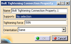
-
Select an assembly constraint or an analysis connection.
In this particular example, select Coincidence.1 (Part4.1, Vis.1) in the specification tree (under the Constraints set).
-
Optionally modify the default value of the force and orientation parameters.
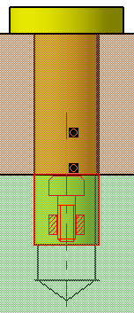
Choose either the same or the opposite orientation so that the graphic representation of the Bolt Tightening Connection matches the bolt direction.
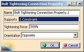
Same Orientation
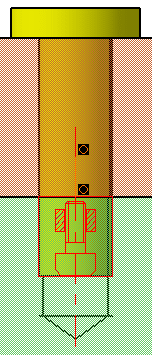
Opposite Orientation
-
Click OK in the Bolt Tightening Connection Property dialog box.
A symbol representing the Bolt Tightening Connection Property is visualized on the corresponding faces.
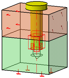

To obtain the same visualization of the assembly, select Shading with Edges in the View toolbar.
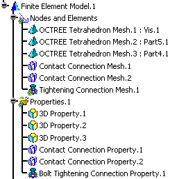
Note that two elements appear in the specification tree:
-
A Tightening Connection Mesh.1 connection mesh part under the Nodes and Elements set
-
A Bolt Tightening Connection Property.1 connection property under the Properties.1 set.
-
![]()