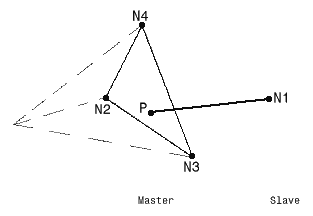
Join element allows connecting a node and a face of an element.
|
Type |
join element |
|
Physical property |
|
|
Mesh connectivity |
SPIDER |
|
Number of nodes |
1 slave, n-1 masters |
|
Degrees of freedom |
3 translations |
|
Type of behavior |
kinematics |
Mesh visualization:
The relations are obtains in the following way:
- Compute the projection of the slave node (N1) on the surface defined by n-1 master nodes.
- Interpolate the displacement of the projected point (P) using the shape function of the face defined by the master nodes.
- Link the displacement of the slave node (N1) to the displacement of the projected point (P) using rigid-body equations, except for the translation in the direction of the tightening given by the property.
- Impose a minimum overlap in the direction given by the property between the slave node (N1) and the projected point (P).

The projected point (P) is a conceptual point, that means it is never created. The displacement of this point is always expressed in terms of displacement of the master nodes through interpolation.
Tightening elements generate a two-steps computation:
- Submit a tightening force,
- Impose a minimum overlap equal to the overlap obtained in the first step.
