This task shows how to detect global and local extrema.
Detecting extrema consists in localizing points where a results field is maximum or minimum. You can ask the program to detect either one or both global extrema and an arbitrary number of local extrema for your field.
Open the sample26.CATAnalysis document from the samples directory.
-
Select View > Render Style > Customize View and make sure the Materials option is active in the Custom View Modes dialog box.
-
Compute the solutions.
To do this, click Compute and select the All option.
 -
Set the static case as the current one.
For more details refer to Changing a Current Analysis Case. -
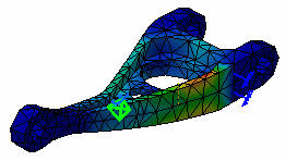
Activate the Stress Von Mises image.
To do this, right click the Von Mises Stress (nodal values).1 image from the specification tree and select the Activate/Deactivate contextual menu.
-
Click Image Extrema
 in the Analysis Tools toolbar.
The Extrema Creation dialog box appears.
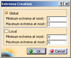
You can ask the program to detect given numbers of global (on the whole part) and/or local (relatively to neighbor mesh elements) extrema at most, by setting the Global and Local options.
- Global: lets you launch the detection of the
minimum and maximum global extrema. Global means that the system
detects all the entities which have a value equal to the Minimum or
Maximum value.

At least, one maximum extremum and one minimum extremum are found. But it is possible that the program detects less extrema than the specified number.
- Local: lets you launch the detection of the minimum
and maximum local extrema. Local means
that the system searches all the entities which are related to
the Minimum or Maximum value compared to the two-leveled
neighboring entities.
It is possible that no local extrema is found (it depends on the image).
For more details about local extrema computation, refer to Post-Processing and Visualization in the Frequently Asked Questions section.
- Global: lets you launch the detection of the
minimum and maximum global extrema. Global means that the system
detects all the entities which have a value equal to the Minimum or
Maximum value.
-
Enter the desired parameters.
In this particular example, enter 1 as global minimum extrema and 1 as global maximum extrema.
-
Click OK.
An image corresponding to the default settings is displayed, with two arrow boxes locating the points of absolute extremum for the current field and containing information about the detected value.
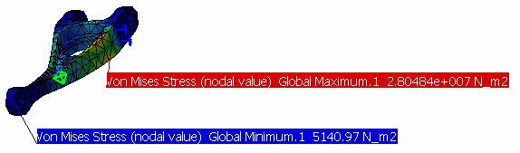
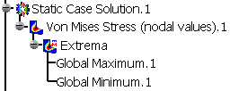
The Extrema set containing the two global extrema appears under the current image in the specification tree.
-
Double-click the Extrema set in the specification tree.
The Extremum Edition dialog box appears.
You can modify the objects set by setting the Global and Local options. -
Clear the Global check box and select the Local check box.
The boxes locating the global extrema disappear, and symbols locating the local extrema are visualized.
The Extrema set in the specification tree now contains, in addition to the two Global Extrema objects, as many Local Extremum (Maximum or Minimum) objects as you have required.
-
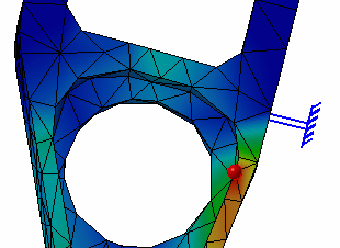
Double-click one of the Local Extremum objects in the specification tree.
The Extremum Edition dialog box appears.
-
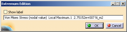
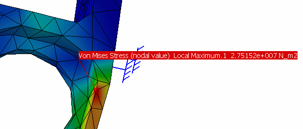
Select the Show label option and click OK in the Extremum Edition dialog box.
A new arrow box is visualized, locating the position of the corresponding point and containing information about the detected value.
The extrema detection command is also available for images obtained under Frequency and Buckling Solutions.
![]()