This task shows how to use the Amplification Magnitude command.
Amplification magnitude consists in scaling the maximum displacement amplitude for visualizing a deformed image.
Open the sample26.CATAnalysis document from the samples directory.
- Make sure the Materials option is selected in the Custom View Modes dialog box (View > Render Style > Customize View).
- Compute the solutions.
To do this, click Compute and select All from the list.
 - Set the Static Case as the current one.
For more details, refer to Changing a Current Analysis Case. - Activate the Von Mises Stress image.
To do this, right-click the Von Mises Stress (nodal values).1 image in the specification tree and select Activate/Deactivate.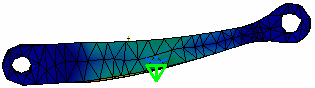
![]()
-
Click Amplification Magnitude
 .
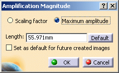
.The Amplification Magnitude dialog box appears. Options available in the dialog box are different depending on whether you select Scaling factor or Maximum amplitude.
- Scaling factor: lets you modify the amplification magnitude
for deformation visualization using a constant scale factor.
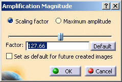
- Factor: lets you specify the scaling factor.
A slider lets you dynamically modify the scale factor from 0 to a maximal value. - Default: lets you return to the default scaling factor.
- Factor: lets you specify the scaling factor.
- Maximum amplitude: lets you modify the amplification
magnitude for deformation visualization using a constant maximum amplitude
(artificial).
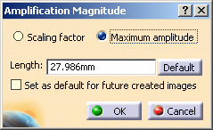
- Length: lets you specify the value of the maximum
allowed deformation on the image (in mm).

The default unit for the Length value is fixed in the Options dialog box (General > Parameters and Measure > Units tab).
For more details, refer to the Infrastructure User's Guide. - Default: lets you return to the default amplification magnitude.
- Length: lets you specify the value of the maximum
allowed deformation on the image (in mm).
- Set as default for future created images: lets you apply the modified amplification magnitude parameter (factor or length) to the future created images.
To summarize:
To visualize the real deformation, the scaling factor must be equal to 1.
- Scaling factor: lets you modify the amplification magnitude
for deformation visualization using a constant scale factor.
-
Click Scaling factor.
-
Enter 300 as Factor value.
As a result, the deformation is increased.
-
Click the Default button and then click OK.
The image retrieves the default deformation.
-
Modify the value of the load.
In this particular example:
-
Double-click the Distributed Force.1 load in the specification tree.
-
Enter 1000N as Z value in the Distributed Force dialog box.
-
Click OK.
-
-
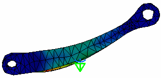
Activate the Von Mises Stress image.
A message informs you that the solution must be updated.
Click OK to update the solution.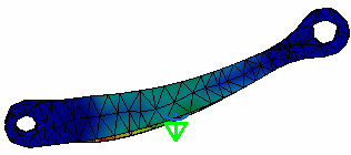
In this case, the real deformation is more important.
So the deformation visualization is more important with a constant scaling factor. -
Click Amplification Magnitude
.The Amplification Magnitude dialog box appears.
-
Click Maximum amplitude.
The Length value is different:
-
Click the Default button.
The Length value is equal to 27.985mm.
-
Click OK.
-
Modify the load value.
In this particular example:
-
Double-click the Distributed Force.1 load in the specification tree.
-
Enter 500N as Z value in the Distributed Force dialog box.
-
Click OK.
-
-
Activate the Von Mises Stress image.
A message informs you that the solution must be updated.
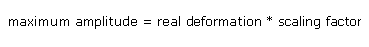
Click OK to update the solution.In this case, the real deformation is less important, but the deformation visualization is the same with a constant maximum amplitude.
![]()