This task shows you how to create a Distributed Mass applied to a virtual part or to a geometry selection.
Distributed Masses are used to model purely inertial (non-structural) system characteristics such as additional equipment. They represent scalar point mass fields equivalent to a total mass concentrated at a given point, distributed on a virtual part or on a geometric selection.
Units are mass units (typically kg in SI).
The user specifies the total mass. This quantity remains
constant independently of the geometry selection.
The distribution behavior depends on the selected support:
- For punctual geometries or spatial groups the mass is equally distributed on each node of the selection.
- For 1D geometries/groups the mass is translated into the equivalent Line Mass Density.
- For 2D geometries/groups the mass is translated into the equivalent Surface Mass Density.
- For virtual parts the total mass is concentrated at the handler of the virtual part.
Mass sets can be included in static cases: in this case, they are used for loadings based inertia effects.
Distributed masses can be applied to the following types of supports:
|
Geometrical Feature |
Mechanical Feature |
Analysis Feature |
||||
|
Spatial Groups |
Geometrical Groups |
Groups by Neighborhood |
Groups by Boundary |
Others |
||
|
Point/Vertex (homogeneous selection) |
|
|
|
|
|
Virtual Part |
To know more, refer to Authorized Supports.
To simulate a weight on a virtual part, you must couple a mass and an acceleration.
Open the sample08.CATAnalysis document from the samples directory.
-
Go to View > Render Style > Customize View and make sure the Shading, Outlines and Materials options are active in the Custom View Modes dialog box.
-
Click Distributed Mass
 in the Masses toolbar.
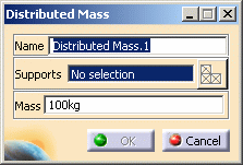
The Distributed Mass dialog box appears.

To know more about the Select Mesh Part button, refer to Selecting Mesh Parts.
-
You can change the identifier of the Distributed Mass by editing the Name field.
-
Enter the value of the total Mass to define the mass magnitude.
-
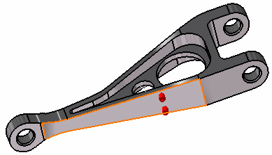
Select the support (a vertex, an edge, a face or a virtual part) on which the concentrated mass is applied at the pre-defined point. Any selectable geometry is highlighted when you pass the cursor over it.
You can select several supports in sequence, to apply the Distributed Mass to all supports simultaneously.
Symbols representing the total mass equivalent to the Distributed Mass are displayed at the application point of the support to visualize the input lumped mass system.
-
Click OK to create the Distributed Mass.
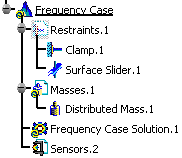
A Distributed Mass.1 object appears in the features tree under the active Masses objects set.

- You can either select the support and then set the Distributed Mass specifications, or set the Distributed Mass specifications and then select the support.
- If you select several geometric supports, you can create as many Distributed Masses as desired with the same dialog box. A series of Distributed Masses can therefore be created quickly. The point where the total mass is initially concentrated is automatically assumed to be the centroid of the system of individual supports centroids.
- Non-Structural Masses are not required for either Stress Analysis or Modal computations.
- If several Analysis Cases have been defined in the Finite Element Model, you must activate a Masses objects set in the features tree before creating a Distributed Mass object (only available if you have ELFINI Structural Analysis product installed).
- Distributed Mass objects can be edited by a double click on the corresponding object or icon in the features tree.
Make sure the computation is finished before starting any of the following operations.
Products Available in Analysis Workbench
The ELFINI Structural Analysis product offers the following additional features with a right mouse click (key 3) on
-
 a Distributed Mass object:
- Distributed mass visualization on mesh: the translation of your Distributed Mass object specifications into solver specifications can be visualized symbolically at the impacted mesh entities, provided the mesh has been previously generated via a Compute action.
-
 on a Masses set:
- Generate Image:
Generates an image of the Local Update action (which translates all user-defined Masses specs into explicit solver commands on mesh entities), by generating symbols for the elementary masses imposed by the Masses objects set. The image can be edited to include part or all of the options available.
Right-click a Masses objects set and select Generate Image. The Image Choice dialog box appears. You can select images by clicking them in the list. - Report:
The partial status and results of intermediate pre-processor computations are reported in HTML format. It represents a subset of the global Report capability and generates a partial report of the Masses objects set Computation.Click Basic Analysis Report
 (on the condition you previously computed a solution using the
Compute icon
 ).
).Click OK in the Reporting Options dialog box that appears (if you have more than one analysis case, ensure that the relevant analysis case is highlighted in the dialog box).
The .html partial report file is displayed.
- Generate Image:
![]()