The document is still open from the previous task.
![]()
-
Click Define Cavity Connection Point
 .
.
You are prompted to select a device. -
Select the part itself.
The dialog box opens: 
- Change the Name to CavConnectionPoint for example.
- Select the back face as Representation: Face.
The representation will be the visualization of the cavity connection point. - Select the Placement Constraints as follows:
The contact: Point.1 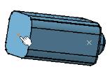
The coincidence: Face 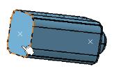
These selections will be used as specifications to create the assembly constraints during the connection of this single insert connector to a cavity. The OK button becomes available.
- Press OK to validate your choice.
-
Save the document as PartStd2.CATPart for example.
This document now contains an electrical connector, with its connection point, that you will insert in the assembly.
See the last task.