This functionality is available in Electrical Part Design workbench only.
The bundle segments must be tangent at their extremities, within the same geometrical bundle.
The centerline of the protection part is a combination of the bundle segment centerlines.
This functionality is only available for bundle segment with circular section.
It is possible to add supports to bundle segments inside a protection part.
-
Click Define Protection Part
 .
.
You are prompted to select a part. -
Click the Part1 in the specification tree.
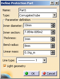
The Define Protection Part dialog box opens: 
-
Enter/change the name for the protection part.
-
Select the protection part type.
It can be Corrugated tube or Tape. When the feature is defined, the type is frozen. Corrugated tube:
A tube defined through an inner diameter, a thickness, a bend radius and a linear mass. Tape:
A strip defined through a width, a thickness, a bend radius delta and a linear mass.
The inner diameter is the bundle segment diameter.
Note: The tape type is also displayed as a tube in the geometry. -
Enter the parameter values:
For the corrugated tube: - Inner diameter: when you enter a value, the section updates accordingly.
- Inner section: when you enter a value, the diameter updates accordingly.
- Thickness
- Bend radius: must be greater than the sum of the inner diameter plus the thickness.
- Linear mass
For the tape: - Width
- Thickness
- Bend radius: must be greater than the sum of the inner diameter plus the thickness.
- Linear mass
-
Select the Line type.
Line type defines the representation of the protection part viewed in 2D when using the Electrical Harness Flattening workbench. New line types can be defined with the Tools > Options menu. -
The Light geometry option allows you to create the protection part geometry according to two modes:
- when the option is checked, the geometry looks like a cylinder and the CATPart document created is smaller. It's the default value.
- when you uncheck this option the geometry looks like a tube.
-
Click OK to validate.
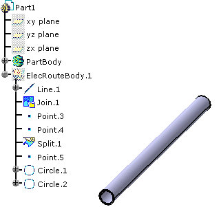
The specification tree is updated: 
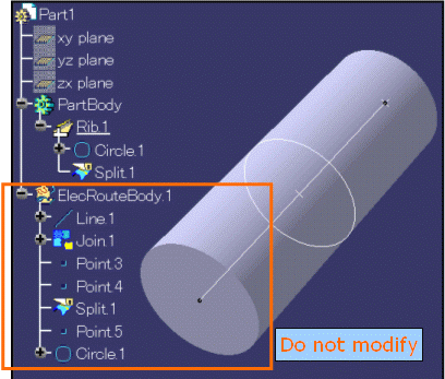
Be aware that if you modify the geometry, you must not change any object under the ElecRouteBody at the risk of getting hazardous behavior when instantiating, modifying or updating the protection part.
