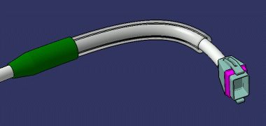
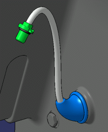
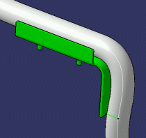
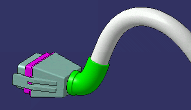
As a reference protection part can be customized, it is quite easy to define one's own bundle protection part with a minimum of effort. To illustrate the flexibility of the protection part, this scenario explains how to create a protection part of a given fixed length. This methodology is widely used in the industry.
-
Start the Electrical Part Design workbench.
-
Click Define Protection Part
 .
.
You are prompted to select a part. -
Select Part1 in the specification tree.
The Define Protection Part dialog box opens.
Select Tape from the Type drop-down list and enter the following values for example, then validate:- Width: 16mm
- Thickness: 2mm
- Bend radius: 7mm

The geometry is created.
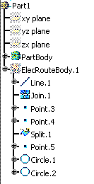
-
Switch to Wireframe and Surface Design workbench.
-
Create a point on the joint which will be used for the instantiation:
To do so:
-
Click Point
 .
.The dialog box opens to create Point.6. -
Enter the following values:
- Point type: On curve
- Curve: Join.1
- Distance on curve
- Length: 250mm
- Reference point: Point.3
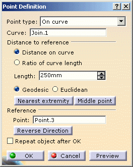
The offset from Point.3, entered in the Length value (250mm) is the parameter which will drive the length of the protective covering. -
Click OK to validate.
Point.6 is added to the geometry. 
-
-
Create a new split on the joint between Point.3 and the newly created Point.6 to define a new centerline between Point.3 and Point.6.
To do so: -
Click Split
 .
.The dialog box opens to create Split.2. -
Enter the following values:
- Element to cut: Join.1
- Cutting elements:
- Point.3 and click the Other side button.
- Point.6.

-
Click OK to validate.
The geometry is updated. 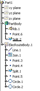
-
-
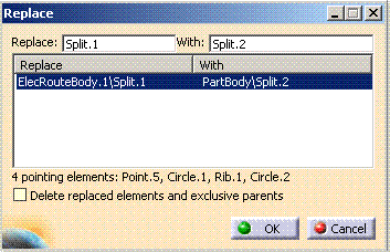
Now replace Split.1 in the PartBody with Split.2, using the contextual menu, to define the rib between Point.3 and Point.6.
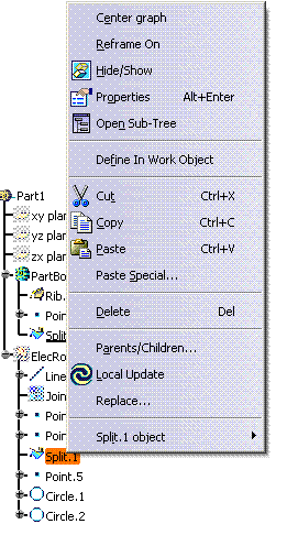
The Replace dialog box opens. -
Select Split.2 (in with field).
-
Click OK to validate.
-
-
Save your protective covering for a further instantiation.
With such a methodology you can also create grommets, green
lines or boots.
When creating grommets in this way, you will need to create two catalog
references. The one you create first will be placed next to the Start
Extremity. To place a grommet next to the End Extremity, create a second
catalog reference, as explained above, selecting Point4 as reference point
and clicking Reverse Direction in step 5.b.
Grommet
Green line
Boot
