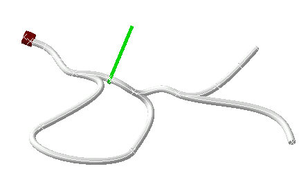
The bundle segments must belong to a geometrical bundle for this command to work properly.
The Browse window is integrated to the Protective Covering command through the Protective Covering dialog box. It lets you select catalogs stored in database when working in ENOVIA context.
![]()
Open any document containing at least a geometrical bundle.
-
In the Electrical Harness Assembly workbench, click Protective Covering
 .
.The dialog box opens:
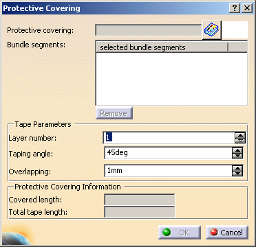
It lets you: - choose the protective covering reference you want to apply, using the catalog browser,
- select the bundle segments on which the protective covering will be applied,
- remove bundle segments from the selection
- define tape parameters.
-
Select the catalog then the protective covering you want to instantiate.

You can only instantiate protective coverings created using the Define Protection Part command in the Electrical Library workbenches. -
To do so: - Click
 and navigate to the catalog, for example:
.../online/cfysm_C2/samples/ElectricalSession/catalog. - Double-click the protective covering.
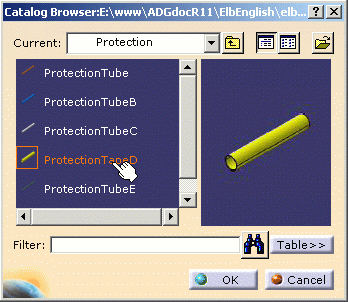
The catalog browser closes and the selected protective covering displays in the upper right corner of the primary window. - Click
-
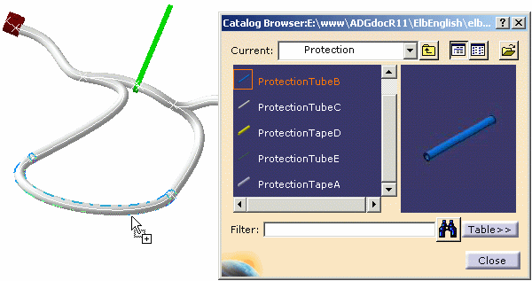
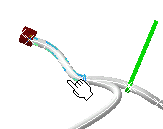
An alternative is to use the catalog browser
 from the toolbar, select the protective covering then drag and drop
it onto the bundle segment:
-
-
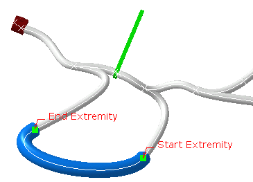
Select one or more bundle segments to be covered with the protective covering:
Notes:
In case of multi-selection, the bundle segments must belong to the same geometrical bundle.
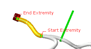
You can select both normal bundle segments and branches , as long as they are contiguous.The dialog box updates and the protective covering start and end points display in the geometry.
-
Double-click one extremity to re-limit the protective covering.
The Create Point on Curve dialog box opens: 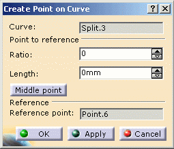
It lets you define the new position for the extremity:
You can change either the ratio or the length (the other parameter is modified accordingly) or select the middle point of the bundle segment.An alternative is to select a point on the curve in the geometry: 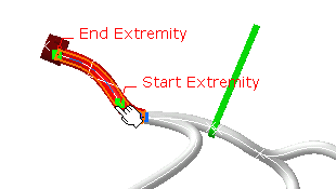
- the Start Extremity here is modified,
- the protective covering turns to red informing you that it needs to be updated.
-
Click OK to validate the re-limitation of the protective covering.
The geometry is updated. 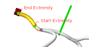
-
Click OK to validate the entries made.
