This task explains how to generate the equivalent parameters which will make it possible to calculate the geometrical bundle components' inertia. Please refer to the Measure Inertia command to know more about those parameters.
It also relies on the mass of the wires routed in the bundle segments and on the mass of the protective coverings. These parameters are calculated using a specific command described below.
This command is available for both bundle segments and
branches.
This command is available when creating a bundle segment on a part (keeping
the associativity).
![]()
Activate the Parameters option in Tools > Options... > Infrastructure > Product Structure > Tree Customization to display the Parameters node in the specification tree.
The calculation is performed as follows:
For the bundle segments, the branches and the protective coverings, the
mass calculation depends on equivalent parameters generated using the
specific Measure Geometrical Bundle Inertia
![]() command.
command.
The other parameters calculation (center of gravity, inertia matrix,
etc.) only depends on the geometry. They are generated by Measure
Inertia
![]() in the Measure
toolbar.
in the Measure
toolbar.
- the mass of the bundle segment is the sum of the mass of the wires routed through this bundle segment as well as the sum of the mass of the internal splices connected to them.
- the mass of the wire extra length used in the back shell is added to
the mass of the bundle segment to which it is connected.
In case several bundle segments are connected to the same back shell, the mass of the wire extra length is added to the mass of the bundle segment for each of them. - the mass of the branches is the sum of the mass of the bundle segments it aggregates.
- the mass of the protective coverings (corrugated tube or tape) is
calculated from the length and the linear mass, if this one is known.
Otherwise, no inertia equivalent is calculated and the default calculation (Measure Inertia command) is applied.
![]()
-
Click Measure Geometrical Bundle Inertia
 .
.
This command computes the parameters needed to get the Mass and Inertia of the selected component. -
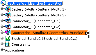
Click the geometrical bundle or electrical bundle for which you want to calculate the inertia parameters.
-
Click Measure Inertia
 .
.The dialog box opens: 
The cursor changes to
 to indicate that you will
be able to measure objects.
to indicate that you will
be able to measure objects.Refer to the Measure Inertia command.
-
Click Customize...
A second dialog box opens: 
Refer to Inertia Equivalents. -
Click to select Equivalent and validate: the inertia equivalents previously computed will be taken into account.
-
Select the electrical component of interest.
it can be: - a geometrical bundle,
- an electrical bundle: selecting an electrical bundle calculates the equivalent parameters for all the geometrical bundles linked to it.

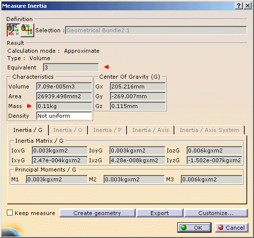
The Measure Inertia dialog box expands to display the results for the selected item: 
Note that the Equivalent field shows that three elements are taken into account for the inertia calculation.
-
Click OK when done.
You will need to launch the command
