This task shows you how to flatten electrical bundles or geometrical bundles.
The ElectricalFlattening.CATProduct document is still open from the previous task.
-
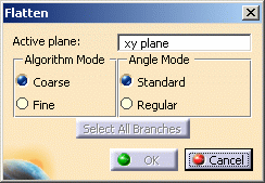
The default values of this dialog box are the values you have already defined in the Harness Flattening Parameters dialog box.
-
Select the Active plane. The default plane is the xy plane.
-
The algorithm mode can be coarse or fine.
Select Coarse for the purpose of this scenario.
There are restrictions concerning the Fine mode: - This mode works properly only when the active plane is collinear to the z axis.
-
The angle mode can be standard or regular.
Select Standard. -
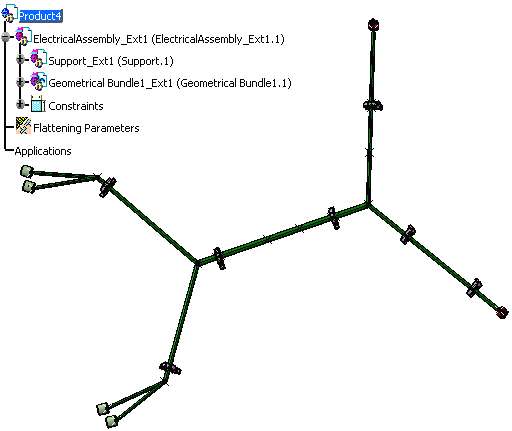
In the specification tree, select an electrical bundle or a geometrical bundle.
The entire harness, if fully connected, is flattened. You can also select a bundle segment to flatten the associated branch, or make a multi-selection of bundle segments. Selecting bundle segments lets you partially flatten a harness.
- Multi-profile bundle segments: in order to avoid twisted and impossible configurations, each bundle segment profile is rotated such that, once flattened, the local V-axis of the profile sketch is aligned with the normal direction of the active plane.
- Bundle Segments on external curves: when flattened, the external curve is migrated to a standard electrical curve. Both the length and bend radius (equal to the diameter) of the external curve are kept.
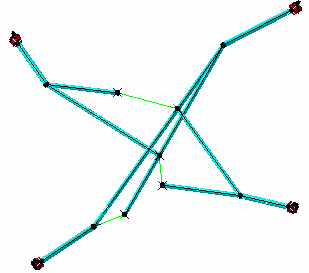
- Mechanical parts: a dashed green line visualizes the link between the bundle segment and mechanical part. Use the compass to reposition the part properly.
- Where several bundle segments are routed through a support, only one bundle segment is kept. The links of other segments are broken and a green line is created.
-
Click OK to validate.
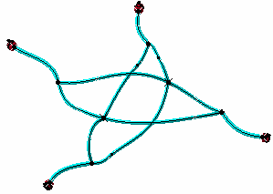
The result looks like this.
About Flattening Harnesses Containing Closed Loops
Harnesses containing closed loops are detected and can be flattened. A message appears informing the user that a closed loop has been detected and asking the user whether or not he wants to proceed.
Closed loops are managed at branch level and not at bundle segment level. When flattening harnesses containing closed loops, the system breaks the:
- Mechanical link at a system-defined point and creates a green line between the two ends of the previously-joined branches. The green line is created between two points: the point that existed before the loop was opened and a new point created at one of the branch ends. The green line informs the user where the system had to open the loop.
- Electrical link.
The user must then close the loop manually by rotating, rolling, etc. the branch.
Notes:
- To break a loop at a user-defined point, straighten one of the branches, taking care to correctly select fixed and free ends of the branch.
- Where protective covering is placed over more than one branch in a loop, breaking the loop at a user-defined point by straightening a branch over which there is no protective covering is recommended.
See also examples illustrating the methodology to use when flattening your harness.