This task shows you how to partially flatten a harness by selecting a bundle segment.
The ElectricalFlattening.CATProduct document is still open.
-

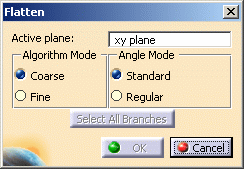
The default values of this dialog box are the values you have already defined in the Harness Flattening Parameters dialog box.
-
Select the Active plane. The default plane is the xy plane.
-
The algorithm mode can be coarse or fine.
Select Coarse for the purpose of this scenario.
There is a restriction concerning the Fine mode: presently this mode works properly only when the active plane is collinear to the z axis. -
The angle mode can be standard or regular.
Select Standard. -
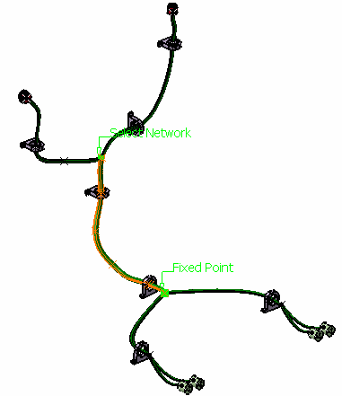
In the geometry area or the specification tree, select a bundle segment.

Where you select the bundle segment is important: the end nearest your selection becomes the fixed point. 
Two points are highlighted in the geometry area: -
The Fixed Point identifying the start point for the partial flatten. No bundle segments upstream of this point are taken into account.
-
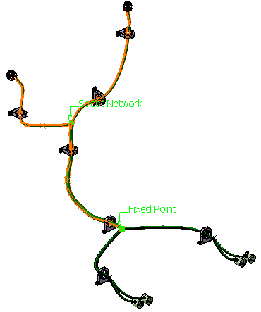
The Select Network identifying the end point for the partial flatten. Bundle segments downstream of this point can be taken into account by selecting them individually or by clicking Select All Branches in the Flatten dialog box.
In the case of multi-branchable documents, the end points of each bundle segment are highlighted.
Notes: - In order to avoid twisted and impossible configurations, each bundle segment profile is rotated such that, once flattened, the local V-axis of the profile sketch is aligned with the normal direction of the active plane.
- When flattened, the external curve is migrated to a standard electrical curve. Both the length and bend radius (equal to the diameter) of the external curve are kept.
-
-
Optional: Double-click Fixed Point label to invert start and end points.
-
Click Select All Branches in the Flatten dialog box.
All bundle segments beyond the Select Network point are taken into account and highlighted in the geometry area. 
-
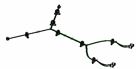
Click OK.
The result looks like this.
