Note that GVS only works on Electrical Harness Flattening data, that is to say data extracted using the Extract command.
For more information, refer to Integrating Generative View Styles (GVS).
If you use Generative View Styles, the options in this tab are not available since they are managed within the drawing document. The following message is displayed.

A CATProduct document is open.
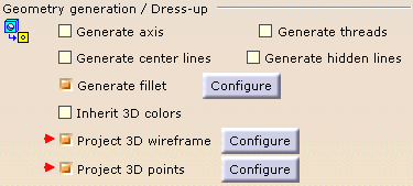
Make sure the Drafting > View options are set as follows:
Open the Tools > Options... menu, then Mechanical Design > Drafting > View tab:
In the Geometry generation / Dress-up frame, select the following check boxes:
Project 3D wireframe
Project 3D points
For more information, refer to the View tab documentation.
-
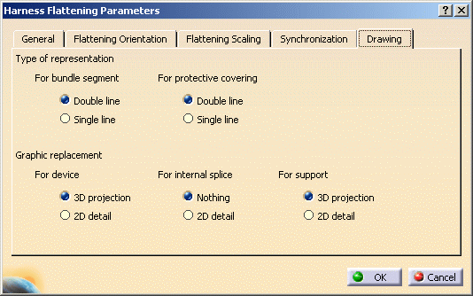
Select the Drawing tab:

This tab lets you define:
-
The type of representation for bundle segments:
-
With Double line
 It is the default value.
 -
Or, Single line.
-
- The type of representation for protective coverings:
-
With Double line
 It is the default value.
 -
Or, Single line.

The line type representation for protective coverings is only available for rectilinear protective coverings. -
- The graphic representation you want to use when replacing
devices or supports:
- Keep the 3D projection (or nothing for the
internal splice, which has no geometrical representation).
 It is the default value.
 - Or, use a 2D detail previously stored in a
catalog.

In this case, the catalog name and path must be defined in the dedicated option.
- Keep the 3D projection (or nothing for the
internal splice, which has no geometrical representation).
-
-
Select the options of interest.
-
Click OK to validate.
