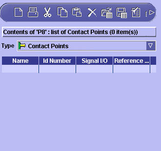
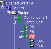
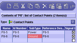
This task explains how to create contact points. In this example, you will create contact points for control unit connector P8.
-
Click the piece of equipment or connector to which you want to add contact points in the tree view.
-
Click the Sub Components button
 .
. The BOM view is displayed to the right of the tree view. 
-
Select the Contact Points type in the list.
-
Click the cell in the Name column and give the contact point a meaningful name.
-
Click the cell in the Id Number column and enter a number.
Note: This attribute is compulsory. Id Numbers of contact points under any one piece of equipment or connector must be unique. These numbers are used to map functional components and corresponding physical parts. -
(Optional) Click cells in attribute columns and complete with appropriate values.
-
Continue to identify the contact points you want to associate with the connector by filling in one row per contact point.
Note: Right-click in the BOM view and select Insert Rows to automatically create entries below existing entries, then define the number of rows in the dialog box that appears. The name attribute is automatically valuated and incremented. - Use the Special Paste command in the contextual menu to use data from other applications, for example Excel files, in Electrical System Functional Definition.
- You can copy entire rows in BOM views into other applications or into the BOM view to create new entries. Right-click a cell in the row you want to copy and select Select Row from the contextual menu. The entire row is highlighted. Right-click again and select Copy.
- To modify an item, simply double-click it and position cursor as desired.
- You can sort items in BOM view columns in ascending alphabetical order (first click), descending alphabetical order (second click) and initial order (third click).
-
Click OK to validate entries made.
Id number and reference designator attributes are automatically valuated if no values were entered. New contact points are created and are added to the tree view.

