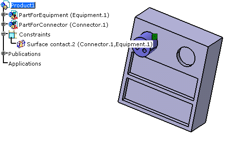
- An electrical link is created between the connected components. See Related Objects.
- If placement constraints have been defined on connection points, the mechanical assembly constraints are automatically created.
Since it's possible to use this command in visualization mode (with the cache activated), the scenario is described according to the two modes:
- The design mode is mandatory to perform the connections.
- In visualization mode, the model is lighter since the geometry is not
loaded.
It allows you to display large assemblies.
When you work in visualization mode, CATIA switches to the design mode only for the elements which contribute to the connection.
In Design Mode
-
Click Connect Electrical Devices
 to connect two devices.
You are prompted to select the first device.
- It is the first selected object that moves to the second one's location
- An electrical connection has been created as well as mechanical constraints.
-
Select the first device either in the geometry area or in the specification tree:
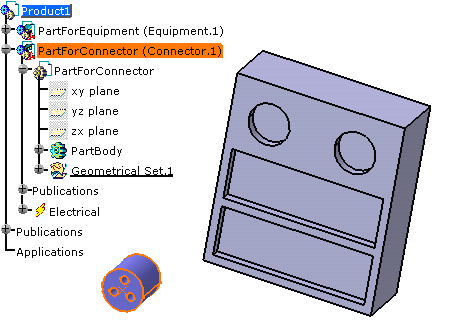
You are prompted to select another device.
-
Move the cursor onto the second device before selecting it, as shown below:
The cavity connection point of the first device and the cavities of the second one are displayed in green: this means that it is possible to connect the connector into the cavity of the equipment. 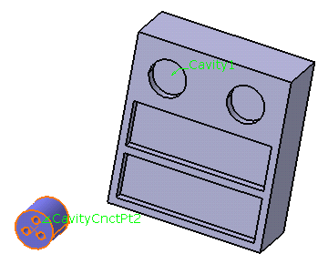
According to the selection, if a cavity is already used or if no connection point is defined on the equipment, it is displayed in red. -
Click to select a connection point available on the equipment, Cavity1 for example.
The devices are connected together and the mechanical constraints are added to the specification tree: 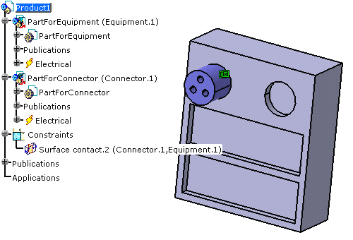
- The representation of the connection point in the geometry area
- The label with the name of the connection point
- The connection point in the specification tree.
In Visualization Mode
-
Select Connect Electrical Devices
 to connect two devices.
You are prompted to select the first device.
- It is the first selected object that moves to the second one's location
- An electrical connection has been created together with mechanical constraints.
-
Select the first device either in the geometry area or in the specification tree.
You are prompted to select the second device. -
Move the cursor onto the second device before selecting it, as shown below:
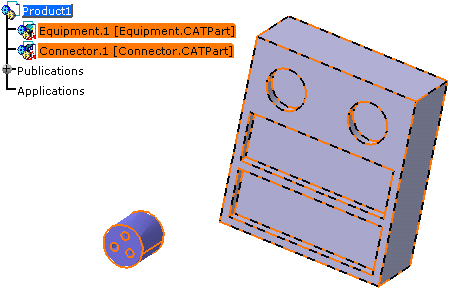
Note that: - You cannot expand the specification tree since you are in visualization mode.
- No annotations are displayed on the device connection points.
-
Click to select the equipment:
The geometry is loaded for both devices and the annotations display: 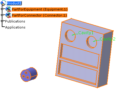
-
Click to select a connection point available on the device, for example Cavity1.
The devices are connected together and the mechanical constraints are added to the specification tree: 