This functionality is available in Electrical Part Design workbench only.
A support is a mechanical object used to hold the bundle segments in position.
![]()
-
Click Define Support
 .
.
You are prompted to select a part. -
Click the Support either in the specification tree or in the geometry area.
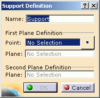
The Support Definition dialog box opens:

-
Enter/change the name for the support.
-
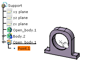
Select the point through the support, to define the reference position of the bundle segment in the support.

If the point is not already defined, click the  button.
For more information, refer to the Point Definition.You are prompted to select the first plane: the way in of the support. -
Select the front face.
You are prompted to select a second plane: the way out of the support. -
Select the opposite face.
To be selectable, it must be parallel to the first face. -
Click OK to validate.
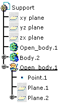
The specification tree is updated:
two extra planes have been defined (Plane.1 and Plane.2).