In
this particular case, we will set constraints between two elements by
selecting the command and then a line and a circle. But what you can also
do is set dimensional constraints by multi-selecting the circle and line,
and then clicking the Constraint icon
![]() .
.
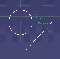
At any time, you may move the cursor: the distance value will vary accordingly. Click for positioning the newly created dimensional constraint.
-
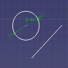
Select the circle.
The circle diameter constraint is displayed.

-
Select the line.
The relation between the two elements is reconsidered. In other words, the circle diameter constraint is no longer displayed.

-
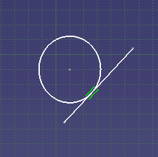
Right-click to display the contextual menu and select the Tangency command to set a tangency constraint between the line and the circle.
A tangency constraint has been created between the circle and the line.

-
Click Constraint
 .
.

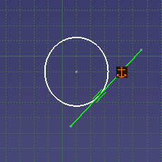
To unfix the line, you can use Line.x object > Unfix from the contextual menu.
- A Projection/Intersection edge created by a constraint is hidden till the software detects a problem with this constraint. In this case, it appears to indicate the error.
- When creating a coincidence constraint between a point in the current sketch and a 3D element outside the sketch, by default the constraint is created on the projection of this 3D element whenever possible. (The constraint is created on the intersection of this 3D element with the sketch plane only when there is no projection for the 3D element.) So if you want to create a constraint on the intersection of the 3D element with the sketch plane, you need create an intersection between this 3D element and the sketch plane, and then create the coincidence constraint with the intersected point.
- We recommend not to create constraints or projections from wireframe elements which lie on a plane orthogonal to the sketch. As a matter of fact, the orientation of the result of these projections in the sketch plane is not stable. (Constraints with external elements use projection first).
- The Shift key lets you deactivate a constraint
(auto-detected via
SmartPick).
The Ctrl key lets you lock the constraint currently created and lets you create others. - Selecting one element lets you create a dimensional constraint.
Selecting two elements lets you create a distance or an angle constraint. - If you want to create a symmetry or equidistance constraints on three elements, you must select Allow symmetry line in the contextual menu after having selected the two first elements.
- You can refer to Selecting Using a Filter and
Selecting Using Other Selection... Command in the
Infrastructure User's Guide to help you select the elements that you want to constrain.